Ford Focus RS (2011 year). Instruction - part 22


  Index      Ford     Ford Focus RS - service repair manual (2011 year) in english


Search            


Content   ..  20  21  22  23   ..


Ford Focus RS (2011 year). Instruction - part 22


Auto-Dimming Interior Mirror

Removal

1. Remove the auto-dimming interior mirror

upper trim panel.

1. Release the clips.
2. Pull the auto-dimming interior mirror upper

trim panel rearwards.

TIE0037284

1

2

1

2. Remove the auto-dimming interior mirror

lower trim panel.

1. Release the clips.
2. Pull the auto-dimming interior mirror lower

trim panel downwards.

TIE0037285

1

1

2

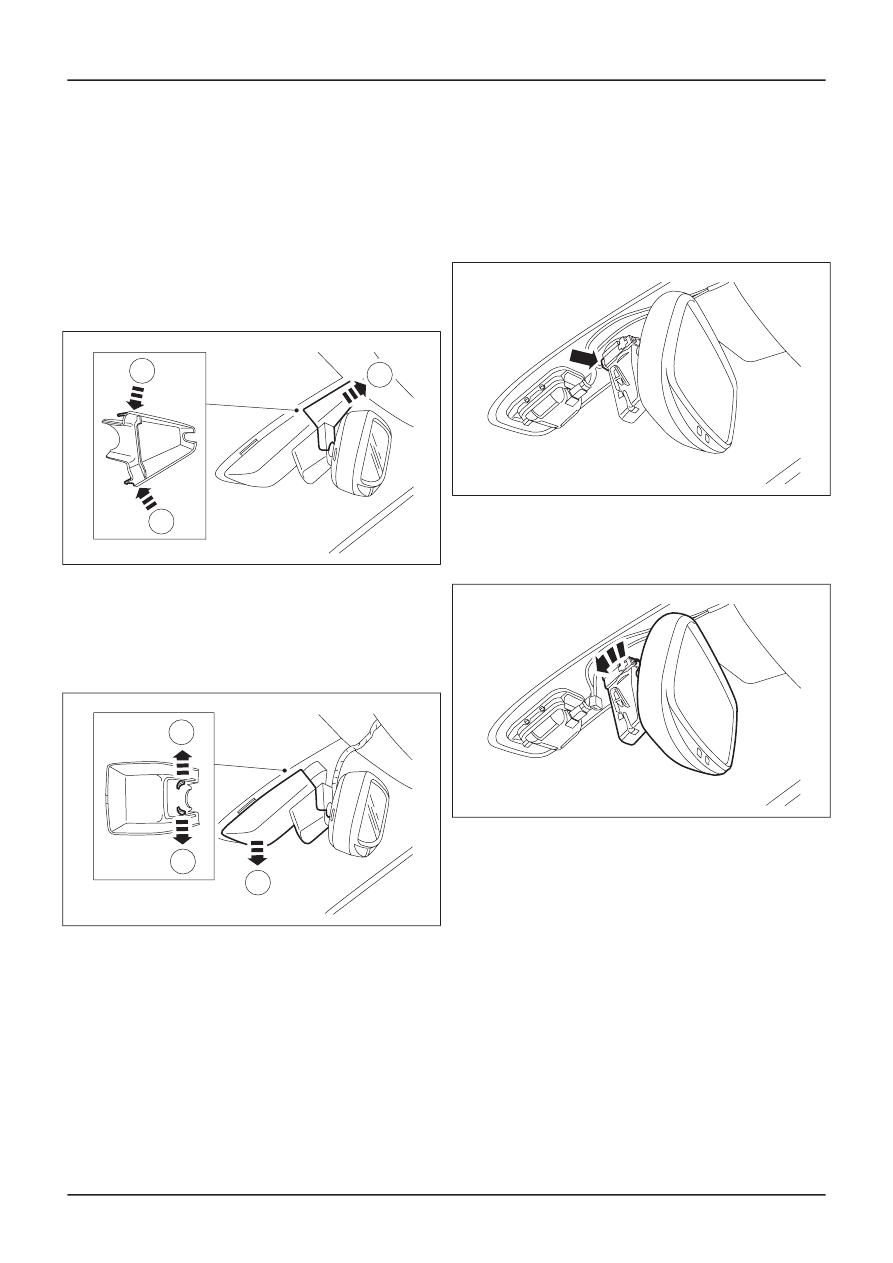
3. Disconnect the auto-dimming interior mirror

electrical connector.

TIE0037288

4. Remove the auto-dimming interior mirror.

• Rotate the mirror bracket 60 degrees

counterclockwise.

TIE0037289

Installation

1. To install, reverse the removal procedure.

G328468en

501-09-

26

Rear View Mirrors

501-09-

26

REMOVAL AND INSTALLATION

SECTION 501-10 Seating

PAGE

CONTENTS

SPECIFICATIONS

501-10-2

Specifications......................................................................................................................

DIAGNOSIS AND TESTING

501-10-3

Seats...................................................................................................................................

501-10-3

Inspection and Verification..................................................................................................

501-10-3

Symptom Chart...................................................................................................................

501-10-4

Pinpoint Tests.....................................................................................................................

REMOVAL AND INSTALLATION

501-10-13

Front Seat...........................................................................................................................

501-10-15

(40 100 0;
40 100 4;
40 101 0)

Front Seat — 2.5L Duratec-RS (224kW/305PS) - VI5...................................

501-10-16

Front Seat Armrest.............................................................................................................

501-10-17

Heated Seat Switch............................................................................................................

501-10-19

(33 797 0;
33 797 4)

Front Seat Height Adjustment Motor..............................................................

501-10-22

(33 784 0;
33 784 4)

Front Seat Track Motor...................................................................................

501-10-23

(40 108 0)

Front Seat Backrest Cover — 2.5L Duratec-ST (VI5)....................................

501-10-26

(40 108 0)

Front Seat Backrest Cover — 2.5L Duratec-RS (224kW/305PS) - VI5..........

501-10-27

(40 105 0)

Front Seat Cushion Cover — 2.5L Duratec-ST (166kW/226PS) - VI5...........

501-10-30

(40 105 0)

Front Seat Cushion Cover — 2.5L Duratec-RS (224kW/305PS) - VI5..........

501-10-32

Rear Seat Backrest Cover..................................................................................................

501-10-39

Rear Seat Backrest Cover — 2.5L Duratec-ST (166kW/226PS) - VI5...............................

501-10-41

Rear Seat Cushion Cover — 2.5L Duratec-ST (166kW/226PS) - VI5................................

501-10-42

Seat Base...........................................................................................................................

DISASSEMBLY AND ASSEMBLY

501-10-48

Rear Seat Cushion.............................................................................................................

501-10-50

Front Seat Backrest — 3-Door...........................................................................................

501-10-53

Front Seat Backrest — 4-Door/5-Door/Wagon...................................................................

501-10-

Seating

501-10-

1

.

VEHICLE APPLICATION:

Torque Specifications

lb-in

lb-ft

Nm

Item

-

26

35

Front seat retaining bolts

-

17

23

Front seat cushion base retaining bolts

-

20

27

Front seat backrest retaining bolts

-

35

47

Front seat safety belt buckle and pretensioner
retaining bolt

-

18

25

Rear seat cushion retaining bolts

-

26

35

Rear seat backrest hinge retaining bolts

-

18

25

Rear seat backrest striker retaining bolts

-

26

35

Rear seat backrest outer pivot pin bush retaining
bolt

-

17

23

Rear seat backrest latch retaining bolts

-

41

55

Rear center safety belt lower anchor and buckle
assembly retaining bolt

89

-

10

Front seat height adjustment link retaining screw

44

-

5

Front seat backrest recliner motor retaining bolt

-

16

22

Rear seat backrest retaining screws - Convertible

G401838en

501-10-

2

Seating

501-10-

2

SPECIFICATIONS

Seats

Refer to Wiring Diagrams Section 501-10, for
schematic and connector information.

Inspection and Verification

1. Verify the customer concern.

2. Visually inspect for obvious signs of mechanical

or electrical damage.

Visual Inspection Chart

Electrical

Mechanical

• Fuse(s)

• Wiring harness

• Electrical

connector(s)

• Motor(s)

• Switch(es)

• Damaged switch(es)

3. If an obvious cause for an observed or reported

concern is found, correct the cause (if possible)
before proceeding to the next step.

4. If the cause is not visually evident, verify the

symptom and refer to the Symptom Chart.

Symptom Chart

Symptom Chart

Action

Possible Sources

Symptom

• CARRY OUT the Seat Control

Switch Component Test.
REFER to the Wiring Diagrams.

• Seat control switch.

• The power seat is inoperative

GO to Pinpoint Test A.

• Motor(s).
• Circuit(s).

• CARRY OUT the Seat Control

Switch Component Test.
REFER to the Wiring Diagrams.

• Seat control switch.

• The power seat does not move

vertically

GO to Pinpoint Test B.

• Motor(s).
• Circuit(s).

• CARRY OUT the Seat Control

Switch Component Test.
REFER to the Wiring Diagrams.

• Seat control switch.

• The power seat does not

recline

GO to Pinpoint Test C.

• Motor.
• Circuit(s).

• CARRY OUT the Seat Control

Switch Component Test.
REFER to the Wiring Diagrams.

• Seat control switch.

• The power seat does not move

horizontally

GO to Pinpoint Test D.

• Motor.
• Circuit(s).

• CARRY OUT the Heated Seat

Control Switch Component
Test. REFER to the Wiring
Diagrams.

• Heated seat control switch(es).

• The heated seat is inoperative

• Circuit(s).

G413215en

501-10-

3

Seating

501-10-

3

DIAGNOSIS AND TESTING

GO to Pinpoint Test E.

Pinpoint Tests

NOTE: Use a digital multimeter for all electrical
measurements.

PINPOINT TEST A : THE POWER SEAT IS INOPERATIVE

DETAILS/RESULTS/ACTIONS

TEST CONDITIONS

A1: CHECK FOR VOLTAGE TO THE DRIVER POWER SEAT

1 Disconnect Driver Power Seat Underseat

Connector C30.

2 Ignition switch in position II.

3 Measure the voltage between the driver power

seat C30 pin 15, circuit 29-AH35 (OG/YE),
harness side and ground.

• Is the voltage greater than 10 volts?

Yes

TIE0019624

No

REPAIR circuit 29-AH35 (OG/YE). TEST the
system for normal operation.

A2: CHECK THE DRIVER POWER SEAT GROUND CIRCUIT FOR CONTINUITY

1 Ignition switch in position 0.

2 Measure the resistance between the driver

power seat C30 pin 16, circuit 31-DA14 (BK),
harness side and ground.

• Is the resistance less than 5 ohms?

Yes

TIE0019625

Vehicles with 6-way power seats

Vehicles with 2-way power seats

No

REPAIR circuit 31-DA14 (BK). TEST the
system for normal operation.

A3: CHECK THE DRIVER POWER SEAT CONTROL SWITCH GROUND CIRCUIT FOR CONTINUITY

1 Connect Driver Power Seat Underseat

2 Disconnect Driver Power Seat Control Switch

C755.

G413215en

501-10-

4

Seating

501-10-

4

DIAGNOSIS AND TESTING

GO to A5

.

Connector C30.

GO to A3

.

GO to A2

.

DETAILS/RESULTS/ACTIONS

TEST CONDITIONS

3 Measure the resistance between the driver

power seat control switch C755 pin 1, circuit 31-
DA14 (BK), harness side and ground.

• Is the resistance less than 5 ohms?

Yes

E51577

No

REPAIR circuit 31-DA14 (BK). TEST the
system for normal operation.

A4: CHECK THE DRIVER POWER SEAT CONTROL SWITCH POWER CIRCUIT FOR CONTINUITY

1 Ignition switch in position II.

2 Measure the voltage between the driver power

seat control switch C755 pin 2, circuit 29-AH35
(OG/YE), harness side and ground.

• Is the voltage greater than 10 volts?

Yes

E51578

VERIFY the customer concern.

No

REPAIR circuit 29-AH35 (OG/YE). TEST the
system for normal operation.

A5: CHECK THE DRIVER POWER SEAT CONTROL SWITCH GROUND CIRCUIT FOR CONTINUITY

1 Connect Driver Power Seat Underseat

Connector C30.

2 Disconnect Driver Power Seat Control Switch

C715.

3 Measure the resistance between the:

• driver power seat control switch C715 pin 3,

circuit 31-AH35 (BK), harness side and ground.

• driver power seat control switch C715 pin 6,

circuit 31-AH35A (BK), harness side and ground.

TIE0014346

• Are the resistances less than 5 ohms?

Yes

No

REPAIR circuit 31-AH35 (BK) or circuit 31-
AH35A (BK). TEST the system for normal
operation.

G413215en

501-10-

5

Seating

501-10-

5

DIAGNOSIS AND TESTING

GO to A6.

GO to A4

.

DETAILS/RESULTS/ACTIONS

TEST CONDITIONS

A6: CHECK THE DRIVER POWER SEAT CONTROL SWITCH POWER CIRCUIT FOR CONTINUITY

1 Ignition switch in position II.

2 Measure the voltage between the driver power

seat control switch C715 pin 2, circuit 29-AH35
(OG/YE), harness side and ground.

• Is the voltage greater than 10 volts?

Yes

TIE0014348

VERIFY the customer concern.

No

REPAIR circuit 29-AH35 (OG/YE). TEST the
system for normal operation.

PINPOINT TEST B : THE POWER SEAT DOES NOT MOVE VERTICALLY

DETAILS/RESULTS/ACTIONS

TEST CONDITIONS

B1: CHECK THE DOWN VOLTAGE TO THE SEAT HEIGHT ADJUSTMENT MOTOR

1 Detach the seat assembly from the floor panel.

2 Disconnect Seat Height Adjustment Motor C759.

3 Ignition switch in position II.

4 Operate the power seat height control switch to

the DOWN position and measure the voltage
between the seat height adjustment motor C759
pin 1, circuit 33-AH38 (YE/BK), harness side
and ground.

• Is the voltage greater than 10 volts?

Yes

E51579

No

REPAIR circuit 33-AH38 (YE/BK). TEST the
system for normal operation.

G413215en

501-10-

6

Seating

501-10-

6

DIAGNOSIS AND TESTING

GO to B2.

DETAILS/RESULTS/ACTIONS

TEST CONDITIONS

B2: CHECK THE UP VOLTAGE TO THE SEAT HEIGHT ADJUSTMENT MOTOR

1 Operate the power seat height control switch to

the UP position and measure the voltage
between the seat height adjustment motor C759
pin 2, circuit 32-AH38 (WH/BK), harness side
and ground.

• Is the voltage greater than 10 volts?

Yes

E51580

INSTALL a new front seat height adjustment
motor.

Installation).

TEST the system for normal operation.

No

REPAIR circuit 32-AH38 (WH/BK). TEST the
system for normal operation.

PINPOINT TEST C : THE POWER SEAT DOES NOT RECLINE

DETAILS/RESULTS/ACTIONS

TEST CONDITIONS

C1: CHECK THE REARWARD VOLTAGE TO THE SEAT BACKREST MOVEMENT MOTOR

1 Detach the seat assembly from the floor panel.

2 Disconnect Seat Backrest Motor C760.

3 Ignition switch in position II.

4 Operate the power seat backrest control switch

to the REARWARD position and measure the
voltage between the seat backrest movement
motor C760 pin 5, circuit 33-AH36 (YE/RD),
harness side and ground.

• Is the voltage greater than 10 volts?

Yes

E51581

No

REPAIR circuit 33-AH36 (YE/RD). TEST the
system for normal operation.

G413215en

501-10-

7

Seating

501-10-

7

DIAGNOSIS AND TESTING

GO to C2

.

Motor

(501-10 Seating, Removal and

REFER to

:

Front Seat Height Adjustment


Content   ..  20  21  22  23   ..