Ford F-150 (2018 year). Manual - part 74
 

  Index      Ford     Ford F-150 - service manual 2018 year in english


Search            


Content   ..  72  73  74  75   ..


Ford F-150 (2018 year). Manual - part 74


Calculating the Maximum
Loaded Trailer Weight for Your
Vehicle

1. Start with the gross combined

weight rating for your vehicle
model and axle ratio. See the
previous charts.

2. Subtract all of the following

that apply to your vehicle:

Vehicle curb weight.

Hitch hardware weight, for
example a draw bar, ball, locks
or weight distributing hardware.

Driver weight.

Passenger(s) weight.

Payload, cargo and luggage
weight.

Aftermarket equipment weight.

This equals the maximum loaded
trailer weight for this combination.

Note: The trailer tongue load is
considered part of the payload for
your vehicle. Reduce the total
payload by the final trailer tongue
weight.

Note: Consult an authorized dealer
to determine the maximum trailer
weight allowed for your vehicle if
you are not sure.

ESSENTIAL TOWING CHECKS

Follow these guidelines for safe towing:

Do not tow a trailer until you drive your
vehicle at least 1000 miles (1600
kilometers).

Consult your local motor vehicle laws
for towing a trailer.

See the instructions included with
towing accessories for the proper
installation and adjustment
specifications.

Service your vehicle more frequently if
you tow a trailer. See your scheduled
maintenance information.

If you use a rental trailer, follow the
instructions the rental agency gives
you.

See Load limits in the Load Carrying
chapter for load specification terms found
on the tire label and Safety Compliance
label and instructions on calculating your
vehicle's load.

Remember to account for the trailer
tongue weight as part of your vehicle load
when calculating the total vehicle weight.

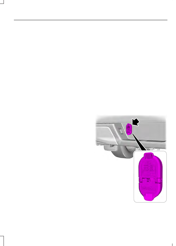
Trailer Towing Connector

E193232

When attaching the trailer wiring connector
to your vehicle, only use a proper fitting
connector that works with the vehicle and
trailer functions. Some seven-position
connectors may have the SAE J2863 logo,
which confirms that it is the proper wiring
connector and works correctly with your
vehicle.

Function

Color

Left turn signal and stop lamp

Yellow

Ground (-)

White

Electric brakes

Blue

Right turn signal and stop
lamp

Green

Battery (+)*

Orange

Running lights

Brown

Reverse lights

Grey

*Your vehicle must recognize the trailer
before the trailer can receive power.

Recognizing a Trailer

1.

Attach the trailer and wiring connector
to your vehicle.

2. Switch on your vehicle.

3. Press the brake pedal for a few

seconds.

A confirmation message appears in the
information display.  See Information
Messages (page 122).

Hitches

Do not use a hitch that either clamps onto
the bumper or attaches to the axle. You
must distribute the load in your trailer so
that 10-15% of the total weight of the
trailer is on the tongue.

Weight-distributing Hitches

WARNING

Do not adjust the spring bars so that
your vehicle's rear bumper is higher
than before attaching the trailer.

Doing so will defeat the function of the
weight-distributing hitch, which may cause
unpredictable handling, and could result
in serious personal injury.

When hooking-up a trailer using a
weight-distributing hitch, always use the
following procedure:

1.

Park the loaded vehicle, without the
trailer, on a level surface.

2. Measure the height to the top of your

vehicle's front wheel opening on the
fender. This is H1.

3. Attach the loaded trailer to your vehicle

without the weight-distributing bars
connected.

4. Measure the height to the top of your

vehicle's front wheel opening on the
fender a second time. This is H2.

5. Install and adjust the tension in the

weight-distributing bars so that the
height of your vehicle's front wheel
opening on the fender is approximately
a quarter the way down from H2,
toward H1.

6. Check that the trailer is level or slightly

nose down toward your vehicle. If not,
adjust the ball height accordingly and
repeat Steps 2-6.

Once the trailer is level or slightly nose
down toward the vehicle:

Lock the bar tension adjuster in place.

Check that the trailer tongue securely
attaches and locks onto the hitch.

Install safety chains, lighting, and trailer
brake controls as required by law or the
trailer manufacturer.

Safety Chains

Note: Do not attach safety chains to the
bumper.

Always connect the safety chains to the
frame or hook retainers of your vehicle
hitch.

To connect the safety chains, cross the
chains under the trailer tongue and allow
enough slack for turning tight corners. Do
not allow the chains to drag on the ground.

Trailer Brakes

WARNING

Do not connect a trailer's hydraulic
brake system directly to your
vehicle's brake system. Your vehicle

may not have enough braking power and
your chances of having a collision greatly
increase.

Electric brakes and manual, automatic or
surge-type trailer brakes are safe if you
install them properly and adjust them to
the manufacturer's specifications. The
trailer brakes must meet local and federal
regulations.

The rating for the tow vehicle's braking
system operation is at the gross vehicle
weight rating, not the gross combined
weight rating.

Separate functioning brake systems
are required for safe control of towed
vehicles and trailers weighing more
than 1500 pounds (680 kilograms)
when loaded.

Integrated Trailer Brake Controller (If
Equipped)

WARNING

Use the integrated trailer brake
controller to properly adjust the
trailer brakes and check all

connections before towing a trailer. Failure
to follow this instruction could result in the
loss of control of your vehicle, personal
injury or death.

E183395

When used properly, the trailer brake
controller assists in smooth and effective
trailer braking by powering the trailer’s
electric or electric-over-hydraulic brakes
with a proportional output based on the
towing vehicle’s brake pressure.

You can adjust the level of initial trailer
brake output by selecting one of three
settings using the information display.
Choose Low, Medium or High for the initial
trailer brake output you require.  See
Information Displays (page 111).

The controller user interface consists of
the following:

A: + and - (Gain adjustment buttons):
Pressing these buttons adjusts the
controller's power output to the trailer
brakes in 0.5 increments. You can increase
the gain setting to 10.0 (maximum trailer
braking) or decrease it to 0 (no trailer
braking). The gain setting displays in the
message center.

The controller shows gain setting, output
bar graph, and trailer connectivity status
in the information display. They appear in
the information display as follows:

Trailer Brake Controller Gain (without
trailer connected): Shows the current
gain setting during a given ignition cycle
and when adjusting the gain. This also
displays if you use the manual control
lever or make gain adjustments with
no trailer connected.

Trailer Brake Controller Gain Output:
Displays when you push your vehicle's
brake pedal, or upon use of the manual
control. Bar indicators illuminate in the
information display to indicate the
amount of power going to the trailer
brakes relative to the brake pedal or
manual control input. One bar indicates
the least amount of output; six bars
indicate maximum output.

Trailer Connected: Displays when the
system senses a correct trailer wiring
connection (a trailer with electric trailer
brakes) during a given ignition cycle.

Trailer Disconnected: Displays,
accompanied by a single audible time,
when the system senses a trailer
connection and then a disconnection,
either intentional or unintentional,
during a given ignition cycle. It also
displays if a truck or trailer-wiring fault
occurs causing the trailer to appear
disconnected. This message can also
display if you use the manual control

lever without a trailer connected. After
disconnecting the trailer connector,
press the brake pedal for
approximately five seconds to allow
the system to detect and update the
trailer status.

B: Manual control lever: Slide the control
lever to the left to turn on the trailer's
electric brakes independent of the tow
vehicle's. See the following Procedure for
adjusting gain section for instructions on
proper use of this feature. If you use the
manual control while the brake is also
applied, the greater of the two inputs
determines the power sent to the trailer
brakes.

Stop lamps: Using the manual control
lever illuminates both the trailer brake
lamps and your vehicle brake lamps
except the center high-mount stop
lamp, if you make the proper electrical
connection to the trailer. Pressing your
vehicle brake pedal also illuminates
both trailer and vehicle brake lamps.

Procedure for Setting Trailer Brake
Controller Mode

Select the correct option using the
information display. Choose electric for
trailers with electromagnetic drum brakes
or EOH for trailers with electric over
hydraulic brake systems.  See Information
Displays (page 111).

Trailer Brake Effort Setting

The trailer brake controller allows the user
to customize how aggressively the trailer
brakes engage. The default value is "Low"
and is the recommended setting for most
trailers. If your trailer's brakes require more
initial voltage, or if you prefer more
aggressive trailer braking, then select either
the "Medium" or the "High" setting.


Content   ..  72  73  74  75   ..