Ford Explorer (2018 year). Manual - part 82
 

  Index      Ford     Ford Explorer - service manual 2018 year in english


Search            


Content   ..  80  81  82  83   ..


Ford Explorer (2018 year). Manual - part 82


Drive cautiously when using a full-size
dissimilar spare wheel and tire assembly
and seek service as soon as possible.

Tire Change Procedure

WARNINGS

When one of the front wheels is off
the ground, the transmission alone
will not prevent the vehicle from

moving or slipping off the jack, even if the
transmission is in park (P).

To help prevent your vehicle from
moving when changing a wheel, shift
the transmission into park (P), set

the parking brake and use an appropriate
block or wheel chock to secure the wheel
diagonally opposite to the wheel being
changed. For example, when changing the
front left wheel, place an appropriate block
or wheel chock on the right rear wheel.

Do not work on your vehicle when
the jack is the only support. If the
vehicle slips off the jack, you or

someone else could be seriously injured.

Do not attempt to change a tire on
the side of the vehicle close to
moving traffic. Pull far enough off the

road to avoid the danger of being hit when
operating the jack or changing the wheel.

Always use the jack provided as
original equipment with your vehicle.
If using a jack other than the one

provided, make sure the jack capacity is
adequate for the vehicle weight, including
any vehicle cargo or modifications. If you
are unsure if the jack capacity is adequate,
contact the authorized dealer.

Note: Passengers should not remain in your
vehicle when the vehicle is being jacked.

Note: Jack at the specified locations to
avoid damage to the vehicle.

1.

Park on a level surface, set the parking
brake and activate the hazard flashers.

2. Place the transmission in park (P) and

turn the engine off.

3. Block the diagonally opposite wheel.

4. Turn the two knobs on the floor filler

counterclockwise, then remove the
floor filler and carpeted floor panel
located in the rear of the vehicle.

5. Remove the wing nut securing the

spare tire by turning it
counterclockwise.

6. Remove the spare tire from the spare

tire well.

7.

Remove the wing nut bolt that secures
the jack kit by turning it
counterclockwise.

8. Remove the jack kit, which includes the

jack, lug wrench, L-shaped bolt and
tow recovery hook.

9. Turn the lead screw (where the lug

wrench attaches) of the jack by hand
to release the lug wrench from the jack.
Press the button on the wrench to
extend the handle. Fold down the
wrench socket.

10.

Loosen each wheel lug nut one-half
turn counterclockwise, but do not
remove them until the wheel is raised
off the ground.

11.

The vehicle jacking points are shown
here, and are depicted on the warning
label on the jack.

12.

Small arrow-shaped marks on the
sills show the location of the jacking
points.

13.

Raise the wheel by turning the jack
handle clockwise.

14.

Remove the lug nuts with the lug
wrench.

15.

Replace the flat tire with the spare
tire, marking sure the valve stem is
facing outward. Reinstall the lug nuts
until the wheel is snug against the
hub. Do not fully tighten the lug nuts
until the wheel has been lowered.

16.

Lower the wheel by turning the jack
handle counterclockwise.

17.

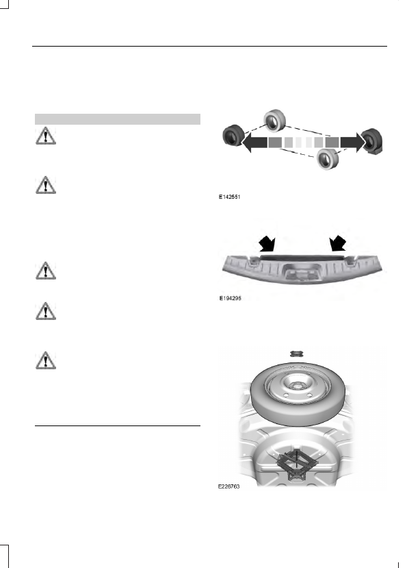
Remove the jack and fully tighten the
lug nuts in the order shown.  See
Technical Specifications (page
334).

Stowing the flat tire

1.

Stand the flat tire vertically in the
mini-spare tub with the tire's valve
stem facing rearward toward the
luggage compartment.

2. Fasten the flat tire to the luggage

compartment back panel by inserting
the L-shaped bolt through one of the
lug bolt holes in the wheel.

3. Turn the L-shaped bolt clockwise into

the threaded hole in the luggage
compartment back panel until the tire
is secured.

4. Unblock the diagonally opposite wheel.

Stowing the jack

With the road wheel in the vertical position
in the spare tire tub, the jack assembly will
not fit in its standard position. Secure the
jack in the alternate position by inserting
the wing bolt through the jack as shown.

TECHNICAL SPECIFICATIONS

Wheel Lug Nut Torque Specifications

WARNING

When you install a wheel, always remove any corrosion, dirt or foreign materials
present on the mounting surfaces of the wheel or the surface of the wheel hub,
brake drum or brake disc that contacts the wheel. Make sure to secure any fasteners

that attach the rotor to the hub so they do not interfere with the mounting surfaces of
the wheel. Installing wheels without correct metal-to-metal contact at the wheel mounting
surfaces can cause the wheel nuts to loosen and the wheel to come off while your vehicle
is in motion, resulting in loss of vehicle control, personal injury or death.

Ib-ft (Nm)

*

Bolt size

100 (135)

1/2-20 x 1.5

*

Torque specifications are for nut and bolt threads free of dirt and rust. Use only Ford

recommended replacement fasteners.

Retighten the lug nuts to the specified torque within 100 miles (160 kilometers) after any
wheel disturbance (such as tire rotation, changing a flat tire, wheel removal).

Wheel pilot bore

A

Inspect the wheel pilot bore and
mounting surface prior to installation.
Remove any visible corrosion or loose
particles.


Content   ..  80  81  82  83   ..