Ford Festiva. Instruction - part 79
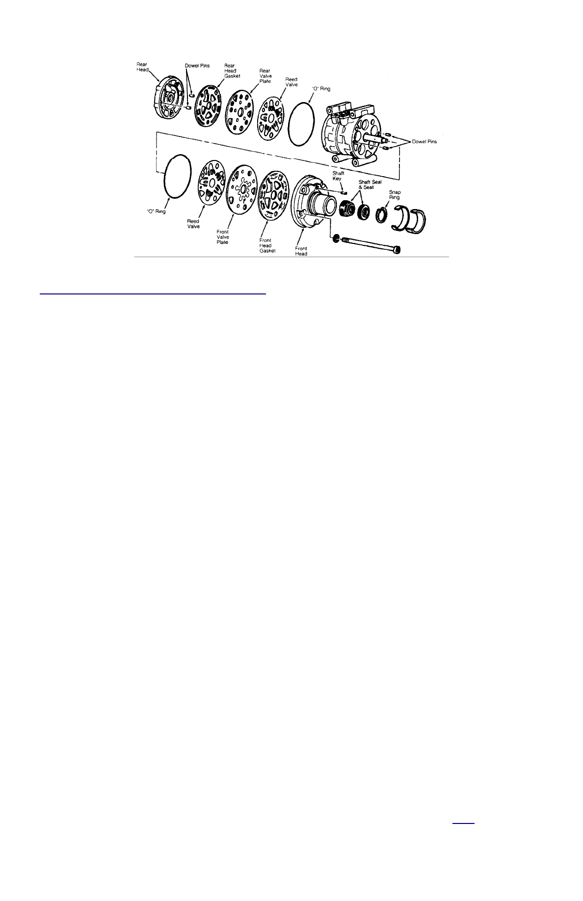
Fig. 3: View of 10P13, 10P15 & 10P15F 10-Cyl Compressor
Courtesy of FORD MOTOR CO.
NIPPONDENSO 10P15, 10P15F CLUTCH ASSEMBLY
Removal
1. Using Spanner (T81P-19623-MH), hold clutch plate and remove crankshaft nut. Using Clutch Plate Remover (T80L-19703-B), pull
clutch plate from compressor. Remove clutch plate shims.
2. Remove snap ring and clutch pulley assembly. If pulley assembly cannot be removed by hand, use Shaft Protector (T80L-19703-G) and
3-jaw puller. Remove snap ring. Disconnect electrical wiring and remove clutch coil.
Installation
1. Install clutch coil over locating pin and install snap ring. Connect electrical wiring.
2. Install pulley assembly, using Pulley Installer (T80L-19703-J) and hammer (if necessary). Install snap ring with beveled side outward.
Install clutch plate shims.
3. Ensure clutch plate aligns with crankshaft key. Using Clutch Plate Installer (T80L-19703-F), install clutch plate. Install crankshaft nut.
Using spanner, tighten nut to 10-14 ft. lbs. (13-20 N.m). DO NOT tighten nut with air tools.
4. Using feeler gauge, check clearance between clutch plate and pulley. Rotate compressor clutch and check clearance in more than one
place. Proper clearance is .021-.036" (.53-.91 mm). If clearance is not correct, add or remove shims.
NIPPONDENSO 10P15A CLUTCH ASSEMBLY
Removal
1. Hold pulley assembly with Strap Wrench (D85L-6000-A). Apply battery voltage to clutch coil assembly and remove crankshaft nut.
Screw Clutch Plate Remover (T88C-19703-BH) into clutch plate and remove clutch plate from compressor. Remove clutch plate shims.
2. Remove snap ring and clutch pulley assembly. If pulley cannot easily be removed, use plastic hammer and tap pulley from shaft.
Remove snap ring. Disconnect electrical wiring and remove clutch coil.
Installation
1. Install clutch coil over locating pin and install snap ring. Connect electrical wiring. Install pulley.
2. Ensure pulley bearing is aligned with compressor head. Gently tap pulley on shaft with plastic hammer (if necessary). Install pulley
retaining snap ring.
3. Install shims and clutch plate. Install crankshaft nut and tighten to 10-12 ft. lbs. (14-16 N.m). DO NOT tighten nut with air tools. Using
feeler gauge, measure clearance between clutch plate and pulley in several different areas. Proper clearance is .016-.028" (.41-.71 mm).
If clearance is not correct, add or remove shims.
NIPPONDENSO 10P15, 10P15F SHAFT SEAL
Removal
1. Discharge system using approved refrigerant recovery/recycling equipment and remove compressor. Drain oil from compressor and
record amount for reassembly.
2. Mount compressor in vise claMFIng on mounting ears. Using Spanner (T81P-19623-MH), hold clutch plate and remove crankshaft nut.
Pull clutch plate from compressor using Clutch Plate Remover (T80L-19703-B). Remove clutch plate shims.
3. Clean compressor front hub area. Remove felt packing and dust seal retainer from inside compressor nose. See
Fig. 3
. Using Shaft Key
Remover (T81P-19623-NH), remove key from shaft.
4. Remove seal seat retaining snap ring. Clean inner bore of compressor nose. Using Shaft Seat Remover/Installer (T87P-19623-B), remove
seal seat.
NOTE:
Remove compressor when clearance is not adequate for clutch assembly removal.