Ford Fiesta (1989-1995). Instruction - part 41
4
Ignition amplifier module
(distributor ignition systems)
- removal and refitting
2
Note: The ignition amplifier module is only
fitted to carburettor engine models.
Removal
1 Disconnect the battery negative (earth) lead
(refer to Part A, Section 1).
2 Remove the distributor, as described in
Section 8.
3 With the distributor on the workbench,
remove both screws securing the module to
the distributor body, then slide the module
from its trigger coil connector and remove it.
4 Check that the rubber grommet is
serviceable. If it is not, it must be renewed but
ensure that the correct type is obtained.
Refitting
5 Apply heat sink compound (see
Specifications) to the module metal face,
ensuring a good earth. This is an essential
part of the procedure, protecting the module
electronic circuitry from excessive heat build-
up and subsequent malfunction.
6 Slide the module into its trigger coil
connector and secure with both screws.
7 Refit the distributor in accordance with
Section 8, then reconnect the battery.
5
Ignition module -
removal and refitting
1
Note: Various designs of ignition module may
be fitted depending on ignition system type.
Although the units may differ in appearance
from the those shown in the accompanying
illustrations, the procedures described below
are applicable to all types.
Removal
1 The ignition module is located on the
engine compartment bulkhead.
2 Disconnect the battery negative (earth) lead
(refer to Part A, Section 1).
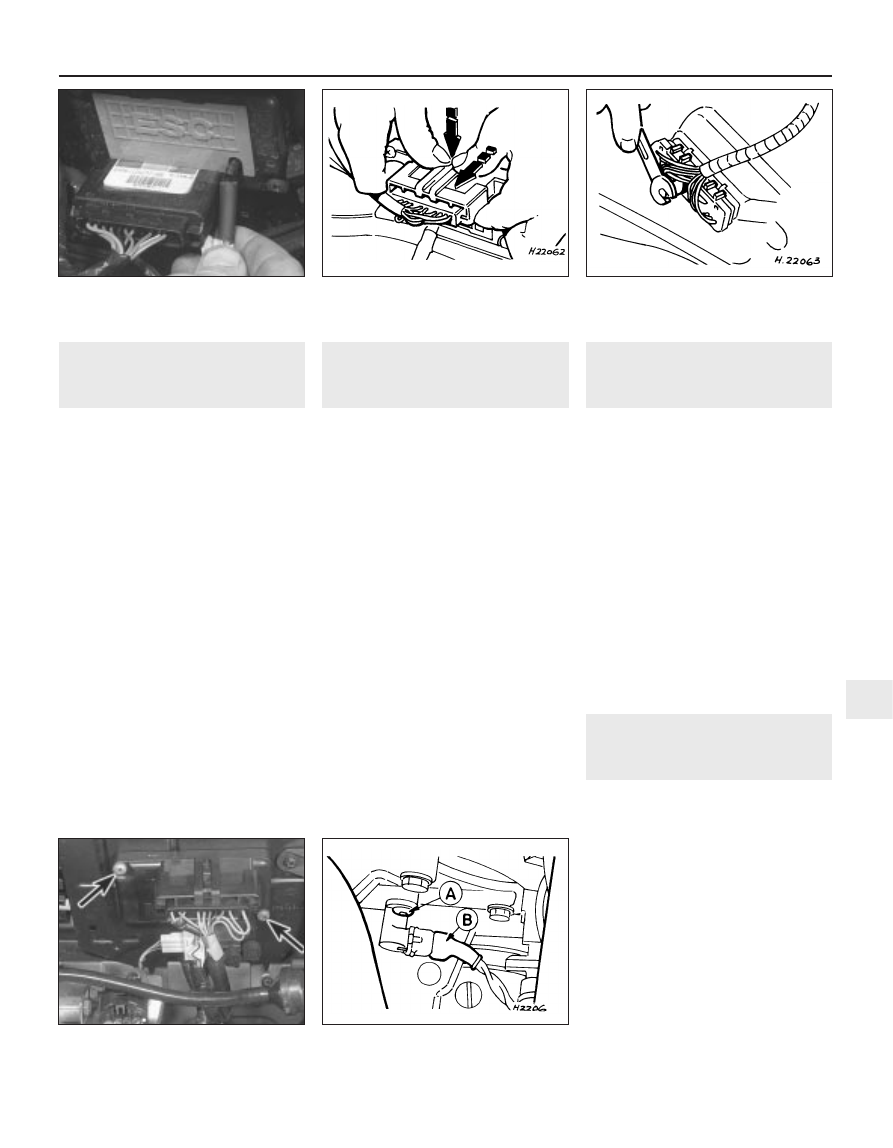
3 Where applicable, detach the vacuum hose
from the module (see illustration).
4 According to type, either compress the
locktab securing the wiring multi-plug in
position, or where applicable, undo the
retaining bolt, then withdraw the plug from the
module (see illustrations).
5 Undo the retaining screws, and remove
the module from the bulkhead (see
illustration).
Refitting
6 Refitting is the reverse of the removal
procedure.
6
Crankshaft position sensor -
removal and refitting
2
Removal
1 Disconnect the battery negative (earth) lead
(refer to Part A, Section 1).
2 Chock the rear wheels then jack up the
front of the car and support it on axle stands
(see “Jacking and vehicle support”).
3 If working on the Zetec engine, remove the
starter motor as described in Part A of this
Chapter.
4 Compress the retaining clip and pull free
the wiring multi-plug connector from the
sensor unit, but take care to pull on the
connector, not the lead (see illustration).
5 Undo the Torx-type retaining screw, and
withdraw the sensor from its location in the
cylinder block bellhousing flange.
Refitting
6 Refitting is the reversal of removal.
7
Distributor cap and rotor
arm - removal and refitting
1
Removal
1 Disconnect the battery negative (earth) lead
(refer to Part A, Section 1).
2 Disconnect the coil HT lead from the centre
of the distributor cap and the spark plug HT
leads from the spark plugs, having identified
them for subsequent refitting. Pull on the
connectors, not the leads. Release the leads
from any cable clips or ties.
3 On carburettor models, unclip the
suppressor shield (where fitted), remove the
distributor cap securing screws and detach
the cap.
4 On CFi fuel injection models, disconnect
the distributor multi-plug for better access to
the rear cap securing clip. Release the
distributor cap securing clips by levering with
a screwdriver, withdraw the cap assembly
Ignition system 5B•5
5.4b Undoing the ignition module multi-
plug securing bolt
5.4a Disconnecting the ignition module
multi-plug
5.3 Disconnecting the vacuum pipe from
the ignition module
6.4 Crankshaft position sensor removal
A Retaining screw B Multi-plug
5.5 Ignition module location on bulkhead
panel. Note retaining screws (arrowed)
5B
1595Ford Fiesta Remake