Ford Fiesta (1989-1995). Instruction - part 14
home by hand, then tighten them securely, to
the specified torque wrench settings, where
given.
11 Refit the auxiliary drivebelt as described in
Chapter 1 on completion.
7
Timing belt covers -
removal and refitting
4
Upper cover
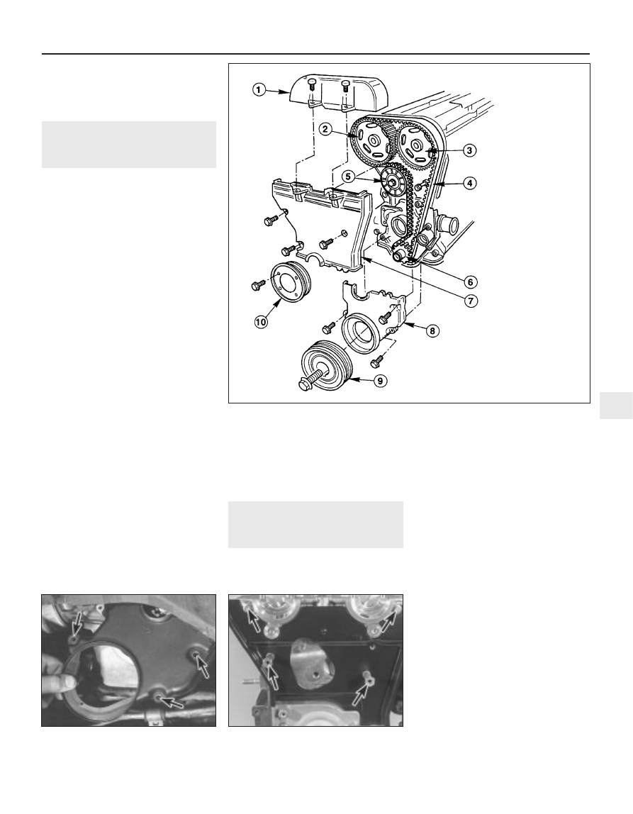
1 Unscrew the cover’s two mounting bolts
and withdraw it (see illustration).
2 Refitting is the reverse of the removal
procedure; ensure that the cover edges
engage correctly with each other, and note the
torque wrench setting specified for the bolts.
Middle cover
3 Slacken the water pump pulley bolts.
4 Remove the timing belt upper cover.
5 Remove the auxiliary drivebelt (see Chap-
ter 1).
6 Unbolt and remove the water pump pulley.
7 Unscrew the middle cover fasteners (one
bolt at the front, one at the lower rear, one
stud at the top rear) and withdraw the cover.
8 Refitting is the reverse of the removal
procedure. Ensure that the cover edges
engage correctly with each other, and note
the torque wrench settings specified for the
various fasteners.
Lower cover
9 Slacken the water pump pulley bolts.
10 Remove the crankshaft pulley (see
Section 6) then unbolt and remove the water
pump pulley.
11 Unscrew the three cover securing bolts,
and withdraw it (see illustration).
12 Refitting is the reverse of the removal
procedure; ensure the cover edges engage
correctly with each other, and note the torque
wrench settings specified for the various
fasteners.
Inner shield
13 Remove the timing belt, its tensioner
components and the camshaft sprockets (see
Sections 8 and 9).
14 The shield is secured to the cylinder head
by two bolts at the top, and by two studs
lower down; unscrew these and withdraw the
shield (see illustration).
15 Refitting is the reverse of the removal
procedure; note the torque wrench settings
specified for the various fasteners.
8
Timing belt - removal, refitting
and adjustment
4
Note: To carry out this operation, a new timing
belt (where applicable), a new cylinder head
cover gasket, and some special tools (see text)
will be required. If the timing belt is being
removed for the first time since the vehicle
left the factory, a tensioner spring and
retaining pin must be obtained for fitting on
reassembly.
Removal
1 Disconnect the battery negative (earth) lead
(refer to Chapter 5A, Section 1).
2 Slacken the water pump pulley bolts.
3 Remove the cylinder head cover (see
Section 4).
4 Remove the spark plugs, covering their
holes with clean rag, to prevent dirt or other
foreign bodies from dropping in (see Chap-
ter 1).
5 Remove the auxiliary drivebelt (see Chap-
ter 1).
6 Position the engine with No 1 piston at TDC
on compression as described in Section 3.
7 Unbolt and remove the water pump pulley
and, where fitted, the auxiliary drivebelt idler
pulley.
8 Obtain Ford service tool 21-162, or
fabricate a substitute alternative from a strip
of metal 5 mm thick (while the strip’s
thickness is critical, its length and width are
not, but should be approximately 180 to
230 mm by 20 to 30 mm). Check that Nos 1
and 4 cylinders are at TDC - No 1 on the
compression stroke - by resting this tool on
the cylinder head mating surface, and sliding
Zetec engine in-car repair procedures 2C•5
7.11 Removing timing belt lower cover -
bolt locations arrowed
7.14 Timing belt inner shield fasteners
(arrowed)
7.1 Timing belt and cover details
2C
1595Ford Fiesta Remake
1 Timing belt upper
cover
2 Inlet camshaft
toothed pulley
3 Exhaust camshaft
toothed pulley
4 Timing belt
5 Timing belt
tensioner
6 Crankshaft toothed
pulley
7 Timing belt middle
cover
8 Timing belt lower
cover
9 Crankshaft pulley
10 Water pump pulley