Fiat 500X (2022 year). Manual in english - page 11
 

  Index      Manuals     Fiat 500X (2022 year). Manual in english


Search            copyright infringement  


Content      ..     9      10      11      12     ..


Fiat 500X (2022 year). Manual in english - page 11


MULTIMEDIA

167

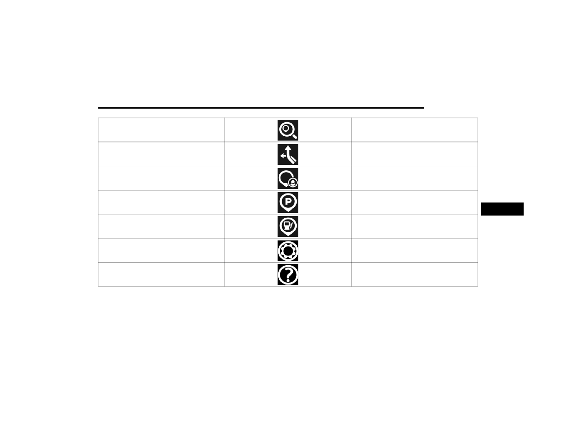
Search

Press to search for a Point Of Interest (POI) or 

specific address.

Current Route

Press to view and edit the current route. This menu 

option is only available when navigating to a 

destination.

My Places

Press to select from a list of saved destinations, 

including the saved Home address, Work address, 

and Recent destinations.

Parking

Press to open the map view with the nearest 

parking locations.

Gas Station

Press to open the map view with the nearest gas 

station locations.

Settings

Press to open up the settings menu and alter map 

and route settings.

Help

Press to open up the help menu.

5

-------------------------------------------------------------------------------------------------------------------------------------------------------------

168

MULTIMEDIA


N

AVIGATING

 A R

OUTE

Navigation Route View

Once a route is programmed, the map view will be 

displayed and highlight the route as a light blue 

bar. The route tracker is on the right side of the 

screen and shows the time and distance to the 

final destination. It also indicates stops and other 

points of interest along the way with icons that 

move closer as you near them. The direction 

distance is displayed at the top of the screen, and 

the main menu can be accessed at any time by 

pressing the Menu button: the four white dots in 

the bottom left-hand corner of the screen. The 

route will continue to display behind the menu as 

you travel along it.

S

EARCH

Search

To search for a destination and start navigation, 

follow these steps:
1. While in the Navigation Main Menu, press the 

Search button.

2. If searching using an address, begin typing the 

address on the keyboard. If searching the 

name of a destination, press “Point of Interest” 

first before typing.

3. Select the location from the list. The display 

will switch to the map view and will show the 

location of the selected destination.

4. Press the Navigate button — the red steering 

wheel icon — to begin navigating to the 

selected location.

NOTE:

Pressing the More button, the three dot icon, next 

to the Navigate button brings up the options to add 

the destination to the My Places menu, add the 

destination to the current route, and more. Within 

More, you can use the destination as a starting 

point and view information about the location.

1 — Navigation View Button
2 — Zoom Button
3 — Next Turn Instructions
4 — Arrival Time and Distance
5 — Main Menu Button
6 — Points Of Interest On Route

-------------------------------------------------------------------------------------------------------------------------------------------------------------

MULTIMEDIA

169

C

URRENT

 R

OUTE

From the Navigation Main Menu, press the Current 

Route button on the touchscreen and select one of 

the following to adjust or change your current 

route.

NOTE:

Current Route can only be selected from the Navi

-

gation Main Menu if the navigation system is 

currently navigating to a destination.

Current Route Options

Clear Route

Press this button on the touchscreen to clear the current route from the Navigation 

system.

Change Route Type

Press this button on the touchscreen to change the current routes type to one of the 

below options:

Fastest route: routes the vehicle to the destination using the roads that will take the 

least amount of time.

Shortest route: routes the vehicle to the destination using the roads that will be the 

shortest amount of total distance traveled.

Most eco-friendly route: routes the vehicle to the destination using the roads that will 

use the least amount of fuel.

Avoid interstate highways: routes the vehicle to the destination avoiding all interstate 

highways.

Find Alternative

Press this button on the touchscreen to view an overhead view of your route, along with 

several others to choose from. Each with the time difference between your current route 

and these new ones. Select the colored button that corresponds to the new route you 

want to take.

5

-------------------------------------------------------------------------------------------------------------------------------------------------------------

170

MULTIMEDIA


Avoid Blocked Road

Press this button on the touchscreen to select a road you wish to avoid on your route that 

is blocked.

Avoid Part Of Route

Press this button on the touchscreen to bring up the list of directions for your current 

route. Select the part of the route you wish to avoid and the system will reroute the 

navigation track to your destination.

Avoid On This Route

Press this button on the touchscreen to select certain types of roads to avoid on your 

navigational route.

Show Instructions

Press this button on the touchscreen to view the directions of your route in list form.

Add Stop To Route

Press this button on the touchscreen to add an additional stop to your current route. 

Pressing the Search button will bring up the keyboard where you can type in the address 

or name of the destination you wish to add.

Reorder Stops

Press this button on the touchscreen to reorder the different stops on the current route.

Play Route Preview

Press this button on the touchscreen to begin a simulated preview of what your route will 

look like. The vehicle icon will begin traveling along your route until it reaches its 

destination. You can also end the preview by returning to the Current Route menu and 

selecting Stop Route Preview.

-------------------------------------------------------------------------------------------------------------------------------------------------------------

MULTIMEDIA

171

M

Y

 P

LACES

My Places

From the Navigation Main Menu, press the My 

Places button on the touchscreen to display a list 

of saved destinations. The following destinations 

are selectable along with any other destinations 

that have been saved.
Home
Press the Home button to navigate to the saved 

Home destination. If no Home destination is saved, 

the Navigation system will ask you to search for the 

destination to save as your Home destination.
Work
Press the Work button to navigate to the saved 

Work destination. If no Work destination is saved, 

the Navigation system will ask you to search for the 

destination to save as your Work destination.

Recent Destinations
Press Recent Destinations button on the 

touchscreen to display a list of destinations the 

Navigation system has recently routed to for you to 

select.
NOTE:

The Add and Edit List buttons allow you to add, 

remove, and reorder destinations that appear 

within the list.

Editing My Places

P

ARKING

Searching For Parking

From the Navigation Main Menu, press the Parking 

button on the touchscreen to bring up a view of 

your current location on the map. Within this map 

view, blue “P” icons will appear pointing out the 

locations of nearby parking lots. Press the desired 

parking lot icon to bring up the location, and select 

the steering wheel icon to navigate to it.

1 — Recent Destination Button
2 — Home Button

5

-------------------------------------------------------------------------------------------------------------------------------------------------------------

172

MULTIMEDIA


G

AS

 S

TATIONS

Searching For Gas Stations

From the Navigation Main Menu, press the Gas 

Stations button on the touchscreen to bring up a 

view of your current location on the map. Within 

this map view, white “Gas Station” icons will 

appear pointing out the locations of nearby gas 

stations. Press the desired gas station icon to bring 

up its location, and select the steering wheel icon 

to navigate to it.

S

ETTINGS

Navigation Settings

From the Navigation Main Menu, press the 

Settings button to open up the Settings menu. The 

following settings categories are selectable within 

the Settings Main Menu:

Appearance

Press this button to adjust the appearance settings of the Navigation system. The 

appearance settings allow you to alter whether or not the system switches to night colors 

when it is dark, change the arrival information that is displayed, change what appears on 

the route (i.e. highway exits), when the system automatically zooms, and adjust the 

guidance view style from 3D, 2D and whether or not to show the 3D car icon.

Voices

Press this button to adjust what the Navigation system calls out while navigating. The 

voices settings allow you to turn on and off whether the system reads early instructions, 

sign information, road numbers, street names, and foreign street names out loud.

-------------------------------------------------------------------------------------------------------------------------------------------------------------

MULTIMEDIA

173

RADIO OPERATION AND MOBILE PHONES  

Under certain conditions, the mobile phone being 

on in your vehicle can cause erratic or noisy 

performance from your radio. This condition may 

be lessened or eliminated by repositioning the 

mobile phone within the vehicle. This condition is 

not harmful to the radio. If your radio performance 

does not satisfactorily improve from repositioning 

the mobile phone, it is recommended that the 

volume be turned down or off during mobile phone 

operation when not using the Uconnect system.

R

EGULATORY

 A

ND

 S

AFETY


I

NFORMATION

US/CANADA
Exposure to Radio Frequency Radiation
The radiated output power of the internal wireless 

radio is far below the FCC and IC radio frequency 

exposure limits. Nevertheless, the wireless radio 

will be used in such a manner that the radio is 8 in 

(20 cm) or further from the human body.
The internal wireless radio operates within 

guidelines found in radio frequency safety 

standards and recommendations, which reflect 

the consensus of the scientific community.
The radio manufacturer believes the internal 

wireless radio is safe for use by consumers. The 

level of energy emitted is far less than the 

electromagnetic energy emitted by wireless 

devices such as mobile phones. However, the use 

of wireless radios may be restricted in some 

situations or environments, such as aboard 

airplanes. If you are unsure of restrictions, you are 

encouraged to ask for authorization before turning 

on the wireless radio  

Ú

page 297.

Route Planning

Press this button to adjust the route planning features of the Navigation system. The 

route planning settings allow you to change whether or not the system will prompt you 

when a faster route is available, which type of route it should plan when setting one (i.e. 

fastest, shortest, most eco-friendly, or to avoid interstate highways), and what to avoid on 

every route.

Sounds & Warnings

Press this button to adjust how the Navigation system should warn you during a route. 

The sounds and warnings settings allows you to set the warning type the system will 

sound, and whether or not to warn you when the vehicle is traveling above the speed 

limit.

System

Press this button to reset the Navigation system. This will reset the Navigation system to 

its factory setting and remove all saved data.

Help

Press the question mark icon to enter the Help menu. Within the Help menu, you may 

view the “About” page that displays system information.

5

-------------------------------------------------------------------------------------------------------------------------------------------------------------

174  

(Continued)

SAFETY

SAFETY FEATURES

A

NTI

-L

OCK

 B

RAKE

 S

YSTEM

 (ABS)  

The ABS provides increased vehicle stability and 

brake performance under most braking conditions. 

The system automatically prevents wheel lock and 

enhances vehicle control during braking.
The ABS performs a self-check cycle to ensure that 

the ABS is working properly each time the vehicle 

is started and driven. During this self-check, you 

may hear a slight clicking sound as well as some 

related motor noises.
The ABS is activated during braking when the 

system detects one or more wheels are beginning 

to lock. Road conditions such as ice, snow, gravel, 

bumps, railroad tracks, loose debris, or panic stops 

may increase the likelihood of ABS activation(s).
You also may experience the following normal 

characteristics when the ABS activates:

The ABS motor noise or clicking sounds (you may 

continue to hear for a short time after the stop).

Brake pedal pulsations.

A slight drop of the brake pedal at the end of the 

stop.

The ABS is designed to function with the Original 

Equipment Manufacturer (OEM) tires. Modification 

may result in degraded ABS performance.

Anti-Lock Brake System (ABS) Warning 

Light

The yellow ABS Warning Light will turn on when the 

ignition is placed in the ON/RUN mode and may 

stay on for as long as four seconds.
If the ABS Warning Light remains on or comes on 

while driving, it indicates that the anti-lock portion 

of the brake system is not functioning and that 

service is required. However, the conventional 

brake system will continue to operate normally if 

the ABS Warning Light is on.
If the ABS Warning Light is on, the brake system 

should be serviced as soon as possible to restore 

the benefits of Anti-Lock Brakes. If the ABS 

WARNING!

The ABS contains sophisticated electronic 

equipment that may be susceptible to interfer

-

ence caused by improperly installed or high 

output radio transmitting equipment. This 

interference can cause possible loss of 

anti-lock braking capability. Installation of 

such equipment should be performed by qual

-

ified professionals.

Pumping of the Anti-Lock Brakes will diminish 

their effectiveness and may lead to a collision. 

Pumping makes the stopping distance longer. 

Just press firmly on your brake pedal when you 

need to slow down or stop.

The ABS cannot prevent the natural laws of 

physics from acting on the vehicle, nor can it 

increase braking or steering efficiency beyond 

that afforded by the condition of the vehicle 

brakes and tires or the traction afforded.

The ABS cannot prevent collisions, including 

those resulting from excessive speed in turns, 

following another vehicle too closely, or hydro

-

planing.

The capabilities of an ABS equipped vehicle 

must never be exploited in a reckless or 

dangerous manner that could jeopardize the 

user’s safety or the safety of others.

WARNING!

-------------------------------------------------------------------------------------------------------------------------------------------------------------

SAFETY

175

Warning Light does not come on when the ignition 

is placed in ON/RUN mode, have the light repaired 

as soon as possible.

E

LECTRONIC

 B

RAKE

 C

ONTROL

 (EBC) 

S

YSTEM


Your vehicle is equipped with an advanced 

Electronic Brake Control (EBC) system. This system 

includes Anti-Lock Brake System (ABS), Brake 

Assist System (BAS), Dynamic Steering Torque 

(DST), Electronic Brake Force Distribution (EBD), 

Electronic Stability Control (ESC), Electronic Roll 

Mitigation (ERM), Hill Start Assist (HSA), and 

Traction Control System (TCS). These systems work 

together to enhance both vehicle stability and 

control in various driving conditions.

Brake System Warning Light

The red Brake System Warning Light will turn on 

when the ignition is placed in the ON/RUN mode 

and may stay on for as long as four seconds.
If the Brake System Warning Light remains on or 

comes on while driving, it indicates that the brake 

system is not functioning properly and that 

immediate service is required. If the Brake System 

Warning Light does not come on when the ignition 

is placed in the ON/RUN mode, have the light 

repaired as soon as possible.

Brake Assist System (BAS) 

The BAS is designed to optimize the vehicle’s 

braking capability during emergency braking 

maneuvers. The system detects an emergency 

braking situation by sensing the rate and amount 

of brake application and then applies optimum 

pressure to the brakes. This can help reduce 

braking distances. The BAS complements the 

Anti-Lock Brake System (ABS). Applying the brakes 

very quickly results in the best BAS assistance. To 

receive the benefit of the system, you must apply 

continuous braking pressure during the stopping 

sequence (do not “pump” the brakes). Do not 

reduce brake pedal pressure unless braking is no 

longer desired. Once the brake pedal is released, 

the BAS is deactivated.

Dynamic Steering Torque (DST)

DST is a feature of the ESC and Electric Power 

Steering (EPS) modules that provides torque at the 

steering wheel for certain driving conditions in 

which the ESC module is detecting vehicle 

instability. The torque that the steering wheel 

receives is only meant to help the driver realize 

optimal steering behavior in order to reach/

maintain vehicle stability. The only notification the 

driver receives that the feature is active is the 

torque applied to the steering wheel.
NOTE:

The DST feature is only meant to help the driver 

realize the correct course of action through small 

torques on the steering wheel, which means the 

effectiveness of the DST feature is highly 

dependent on the driver’s sensitivity and overall 

reaction to the applied torque. It is very important 

to realize that this feature will not steer the vehicle, 

meaning the driver is still responsible for steering 

the vehicle.

Electronic Brake Force Distribution (EBD)

EBD manages the distribution of the braking 

torque between the front and rear axles by limiting 

braking pressure to the rear axle. This is done to 

prevent overslip of the rear wheels to avoid vehicle 

instability, and to prevent the rear axle from 

entering ABS before the front axle.

WARNING!

The Brake Assist System (BAS) cannot prevent 

the natural laws of physics from acting on the 

vehicle, nor can it increase the traction afforded 

by prevailing road conditions. BAS cannot 

prevent collisions, including those resulting from 

excessive speed in turns, driving on very slippery 

surfaces, or hydroplaning. The capabilities of a 

BAS-equipped vehicle must never be exploited in 

a reckless or dangerous manner, which could 

jeopardize the user's safety or the safety of 

others.

6

-------------------------------------------------------------------------------------------------------------------------------------------------------------

176

SAFETY


(Continued)

Electronic Roll Mitigation (ERM)

ERM anticipates the potential for wheel lift by 

monitoring the driver’s steering wheel input and 

the speed of the vehicle. When ERM determines 

that the rate of change of the steering wheel angle 

and vehicle’s speed are sufficient to potentially 

cause wheel lift, it then applies the appropriate 

brake and may also reduce engine power to lessen 

the chance that wheel lift will occur. ERM can only 

reduce the chance of wheel lift occurring during 

severe or evasive driving maneuvers; it cannot 

prevent wheel lift due to other factors, such as 

road conditions, leaving the roadway, striking 

objects or other vehicles.

Electronic Stability Control (ESC) 

ESC enhances directional control and stability of 

the vehicle under various driving conditions. ESC 

corrects for oversteering or understeering of the 

vehicle by applying the brake of the appropriate 

wheel(s) to counteract the above conditions. 

Engine power may also be reduced to help the 

vehicle maintain the desired path.

Oversteer - when the vehicle is turning more 

than appropriate for the steering wheel position.

Understeer - when the vehicle is turning less 

than appropriate for the steering wheel position.

ESC uses sensors in the vehicle to determine the 

vehicle path intended by the driver and compares 

it to the actual path of the vehicle. When the actual 

path does not match the intended path, ESC 

applies the brake of the appropriate wheel to 

assist in counteracting the oversteer or understeer 

condition.
The ESC Activation/Malfunction Indicator Light 

located in the instrument cluster will start to flash 

as soon as the ESC system becomes active. The 

ESC Activation/Malfunction Indicator Light also 

flashes when the TCS is active. If the ESC 

Activation/Malfunction Indicator Light begins to 

flash during acceleration, ease up on the 

accelerator and apply as little throttle as possible. 

Be sure to adapt your speed and driving to the 

prevailing road conditions.

WARNING!

Many factors, such as vehicle loading, road 

conditions and driving conditions, influence the 

chance that wheel lift or rollover may occur. ERM 

cannot prevent all wheel lift or rollovers, 

especially those that involve leaving the roadway 

or striking objects or other vehicles. The 

capabilities of an ERM-equipped vehicle must 

never be exploited in a reckless or dangerous 

manner which could jeopardize the user's safety 

or the safety of others.

WARNING!

Electronic Stability Control (ESC) cannot 

prevent the natural laws of physics from 

acting on the vehicle, nor can it increase the 

traction afforded by prevailing road condi

-

tions. ESC cannot prevent accidents, including 

those resulting from excessive speed in turns, 

driving on very slippery surfaces, or hydro

-

planing. ESC also cannot prevent accidents 

resulting from loss of vehicle control due to 

inappropriate driver input for the conditions. 

Only a safe, attentive, and skillful driver can 

prevent accidents. The capabilities of an ESC 

equipped vehicle must never be exploited in a 

reckless or dangerous manner which could 

jeopardize the user’s safety or the safety of 

others.

-------------------------------------------------------------------------------------------------------------------------------------------------------------

SAFETY

177

ESC Operation Modes
To disable ESC and other active safety systems, 

follow the instruction below.
There are two operation modes of active safety 

systems on the vehicle:

ESC On

Partial Off

ESC On
All active safety systems are enabled. This is the 

normal operating mode when driving a vehicle.
This mode should be used in most driving 

conditions. The system will be in "ESC On" mode 

every time the engine is started
NOTE:

You are advised to select "Partial Off " mode only 

for specific driving requirements.
Partial Off
By pressing the ESC OFF button located below the 

radio screen when driving, the intervention of the 

ESC and TCS systems is limited to braking action 

on the single wheels.
The other systems remain enabled. Activation of 

this mode is indicated by the warning lamp on the 

instrument panel switching on (if equipped, 

together with a message on the display).
To restore "ESC On" operating mode, press the 

button below the radio screen again.
"ESC On" mode will automatically reactivate every 

time the engine is started.
NOTE:

When traveling on snowy roads with snow chains, 

it may be helpful to activate "Partial Off" mode: in 

these conditions, you can obtain better traction by 

slipping the drive wheels.

Hill Start Assist (HSA)  

HSA is designed to mitigate roll back from a 

complete stop while on an incline. If the driver 

releases the brake while stopped on an incline, 

HSA will continue to hold the brake pressure for a 

short period. If the driver does not apply the 

throttle before this time expires, the system will 

release brake pressure and the vehicle will roll 

down the hill as normal.
The following conditions must be met in order for 

HSA to activate:

The feature must be enabled.

The vehicle must be stopped.

The parking brake must be off.

The driver door must be closed.

The vehicle must be on a sufficient grade.

Vehicle modifications, or failure to properly 

maintain your vehicle, may change the 

handling characteristics of your vehicle, and 

may negatively affect the performance of the 

ESC system. Changes to the steering system, 

suspension, braking system, tire type and size 

or wheel size may adversely affect ESC perfor

-

mance. Improperly inflated and unevenly worn 

tires may also degrade ESC performance. Any 

vehicle modification or poor vehicle mainte

-

nance that reduces the effectiveness of the 

ESC system can increase the risk of loss of 

vehicle control, vehicle rollover, personal 

injury and death.

WARNING!

WARNING!

When in “Partial Off” mode, the TCS functionality 

of ESC, except for the limited slip feature 

described in the Traction Control System (TCS) 

section, has been disabled and the ESC OFF 

Indicator Light will be illuminated. When in 

“Partial Off” mode, the engine power reduction 

feature of TCS is disabled, and the enhanced 

vehicle stability offered by the ESC system is 

reduced.

6

-------------------------------------------------------------------------------------------------------------------------------------------------------------

178

SAFETY


The gear selection must match vehicle uphill 

direction (i.e., vehicle facing uphill is in forward 

gear; vehicle backing uphill is in REVERSE gear).

HSA will work in REVERSE gear and all forward 

gears. The system will not activate if the trans

-

mission is in PARK or NEUTRAL. For vehicles 

equipped with a manual transmission, if the 

clutch is pressed, HSA will remain active.

Disabling And Enabling HSA

This feature can be turned on or turned off. To 

change the current settings in the instrument 

cluster display see  

Ú

page 64.

Traction Control System (TCS) 

The TCS monitors the amount of wheel spin of 

each of the driven wheels. If wheel spin is 

detected, the TCS may apply brake pressure to the 

spinning wheel(s) and/or reduce vehicle power to 

provide enhanced acceleration and stability. A 

feature of the TCS, Brake Limited Differential (BLD) 

functions similarly to a limited slip differential and 

controls the wheel spin across a driven axle. If one 

wheel on a driven axle is spinning faster than the 

other, the system will apply the brake of the 

spinning wheel. This will allow more vehicle torque 

to be applied to the wheel that is not spinning. BLD 

may remain enabled even if TCS and ESC are in 

reduced modes.

AUXILIARY DRIVING SYSTEMS

B

LIND

 S

POT

 M

ONITORING

 (BSM) — 

I

F

 E

QUIPPED


BSM uses two radar sensors, located inside the 

rear fascia/bumper, to detect highway licensable 

vehicles (automobiles, trucks, motorcycles, etc.) 

that enter the blind spot zones from the rear/front/

side of the vehicle.

Rear Detection Zones

When the vehicle is started, the BSM Warning Light 

will momentarily illuminate in both outside 

rearview mirrors to let the driver know that the 

system is operational. The BSM system sensors 

operate when the vehicle is in any forward gear 

and enters standby mode when the vehicle is in 

PARK.
The BSM detection zone covers approximately one 

lane width on both sides of the vehicle, 10 ft (3 m). 

The zone length starts at the outside mirror and 

extends approximately 20 ft (6 m) beyond the rear 

fascia/bumper of the vehicle. The BSM system 

monitors the detection zones on both sides of the 

vehicle when the vehicle speed reaches 

approximately 6 mph (10 km/h) or higher and will 

alert the driver of vehicles in these areas.

WARNING!

There may be situations where the Hill Start 

Assist (HSA) will not activate and slight rolling 

may occur, such as on minor hills or with a 

loaded vehicle, or while pulling a trailer. HSA is 

not a substitute for active driving involvement. It 

is always the driver’s responsibility to be 

attentive to distance to other vehicles, people, 

and objects, and most importantly brake 

operation to ensure safe operation of the vehicle 

under all road conditions. Your complete 

attention is always required while driving to 

maintain safe control of your vehicle. Failure to 

follow these warnings can result in a collision or 

serious personal injury.

-------------------------------------------------------------------------------------------------------------------------------------------------------------

SAFETY

179

NOTE:

The BSM system DOES NOT alert the driver 

about rapidly approaching vehicles that are 

outside the detection zones.

If a trailer is connected to the vehicle, it is neces

-

sary to deactivate BSM system manually by 

settings menu to avoid a misdetection  

Ú

page 123.

The area on the rear fascia/bumper where the 

radar sensors are located must remain free of 

snow, ice, and dirt/road contamination so that the 

BSM system can function properly. Do not block 

the radar sensors located on the rear fascia/

bumper with foreign objects (bumper stickers, 

bicycle racks, etc.).

Rear Sensor Locations

The BSM system notifies the driver of objects in the 

detection zones by illuminating the BSM warning 

light located in the outside mirrors, in addition to 

sounding an audible (chime) alert (whenever the 

turn signal is activated) and reducing the radio 

volume  

Ú

page 181.

BSM Warning Light

The BSM system monitors the detection zone from 

three different entry points (side, rear, front) while 

driving to see if an alert is necessary. The BSM 

system will issue an alert during these types of 

zone entries.
Entering From The Side
Vehicles that move into your adjacent lanes from 

either side of the vehicle.

Side Monitoring

Entering From The Rear
Vehicles that come up from behind your vehicle on 

either side and enter the rear detection zone with 

a relative speed of less than 31 mph (50 km/h).

Rear Monitoring

6

-------------------------------------------------------------------------------------------------------------------------------------------------------------

180

SAFETY


Overtaking Traffic
If you pass another vehicle slowly with a relative 

speed less than 15 mph (25 km/h) and the vehicle 

remains in the blind spot for approximately 

1.5 seconds, the warning light will be illuminated. 

If the difference in speed between the two vehicles 

is greater than 15 mph (25 km/h), the warning 

light will not illuminate.

Overtaking/Approaching

Overtaking/Passing

The BSM system is designed not to issue an alert 

on stationary objects such as guardrails, posts, 

walls, foliage, berms, etc. However, occasionally 

the system may alert on such objects. This is 

normal operation and your vehicle does not require 

service.
The BSM system will not alert you of objects that 

are traveling in the opposite direction of the vehicle 

in adjacent lanes  

Ú

page 297.

Opposing Traffic

WARNING!

The Blind Spot Monitoring system is only an aid 

to help detect objects in the blind spot zones. 

The BSM system is not designed to detect 

pedestrians, bicyclists, or animals. Even if your 

vehicle is equipped with the BSM system, always 

check your vehicle’s mirrors, glance over your 

shoulder, and use your turn signal before 

changing lanes. Failure to do so can result in 

serious injury or death.

-------------------------------------------------------------------------------------------------------------------------------------------------------------

SAFETY

181

Rear Cross Path (RCP)

RCP is intended to aid the driver when backing out 

of parking spaces where their vision of oncoming 

vehicles may be blocked. Proceed slowly and 

cautiously out of the parking space until the rear 

end of the vehicle is exposed. The RCP system will 

then have a clear view of the cross traffic and if an 

oncoming vehicle is detected, alert the driver.

RCP Detection Zones

RCP monitors the rear detection zones on both 

sides of the vehicle, for objects that are moving 

toward the side of the vehicle with a minimum 

speed of approximately 1 mph (2 km/h), to objects 

moving a maximum of approximately 22 mph 

(35 km/h), such as in parking lot situations.
When RCP is on and the vehicle is in REVERSE, the 

driver is alerted using both the visual and audible 

alarms, including reducing the radio volume.

NOTE:

In a parking lot situation, oncoming vehicles can be 

blocked by vehicles parked on either side. If the 

sensors are blocked by other structures or 

vehicles, the system will not be able to alert the 

driver.

Blind Spot Modes

Blind Spot has three selectable modes of 

operation that are available in the Uconnect 

system.
Blind Spot Alert Lights Only
When operating in Blind Spot Alert mode, the BSM 

system will provide a visual alert in the appropriate 

side view mirror based on a detected object. 

However, when the system is operating in Rear 

Cross Path (RCP) mode, the system will respond 

with both visual and audible alerts when a 

detected object is present. Whenever an audible 

alert is requested, the radio is muted.
Blind Spot Alert Lights/Chime
When operating in Blind Spot Alert Lights/Chime 

mode, the BSM system will provide a visual alert in 

the appropriate side view mirror based on a 

detected object. If the turn signal is then activated, 

and it corresponds to an alert present on that side 

of the vehicle, an audible chime will also be 

sounded. Whenever a turn signal and detected 

object are present on the same side at the same 

time, both the visual and audible alerts will be 

issued. In addition to the audible alert, the radio (if 

on) will also be muted.
NOTE:

Whenever an audible alert is requested by the 

BSM system, the radio is also muted.
When the system is in RCP, the system will respond 

with both visual and audible alerts when a 

detected object is present. Whenever an audible 

alert is requested, the radio is also muted. Turn/

hazard signal status is ignored; the RCP state 

always requests the chime.
Blind Spot Alert Off
When the BSM system is turned off, there will be 

no visual or audible alerts from either the BSM or 

RCP systems.

WARNING!

RCP is not a backup aid system. It is intended to 

be used to help a driver detect an oncoming 

vehicle in a parking lot situation. Drivers must be 

careful when backing up, even when using RCP. 

Always check carefully behind your vehicle, look 

behind you, and be sure to check for 

pedestrians, animals, other vehicles, 

obstructions, and blind spots before backing up. 

Failure to do so can result in serious injury or 

death.

6

-------------------------------------------------------------------------------------------------------------------------------------------------------------

182

SAFETY


NOTE:

The BSM system will store the current operating 

mode when the vehicle is shut off. Each time the 

vehicle is started the previously stored mode will 

be recalled and used.

Blind Spot Monitoring Fault Warnings

Blinded Sensor
In the case of a blinded sensor:

BSM Mirror Warning Lights are turned on contin

-

uously.

An instrument cluster message will display 

“Blind Spot Monitoring Unavailable - Wipe Rear 

Bumper Corners.”

NOTE:

The rear fascia/bumper must be clean and free of 

any obstructing debris.
System Not Available
In the case of the system being temporarily 

unavailable:

BSM Mirror Warning Lights are turned on contin

-

uously.

An instrument cluster message will display 

“Blind Spot Monitoring Temporarily Unavail

-

able.”

In the case of the system being completely 

unavailable:

A chime will turn on.

An instrument cluster message will display 

“Blind Spot Monitoring Unavailable - Service 

Required.”

NOTE:

The vehicle must be taken to the nearest autho

-

rized dealer for service.

F

ULL

 B

RAKE

 C

ONTROL

 S

YSTEM

 W

ITH


M

ITIGATION

The Full Brake Control system with Mitigation 

provides the driver with audible warnings (through 

the radio), visual warnings (within the instrument 

cluster display), and may apply a brake jerk to warn 

the driver when it detects a potential frontal 

collision. The warnings and limited braking are 

intended to provide the driver with enough time to 

react, avoid or mitigate the potential collision.
NOTE:

The Full Brake Control system monitors the 

information from the forward looking sensors as 

well as the Electronic Brake Controller (EBC), to 

calculate the probability of a forward collision. 

When the system determines that a forward 

collision is probable, the driver will be provided 

with audible and visual warnings and may 

provide a brake jerk warning.

If the driver does not take action based upon 

these progressive warnings, then the system 

will provide a limited level of active braking to 

help slow the vehicle and mitigate the potential 

forward collision. If the driver reacts to the warn

-

ings by braking and the system determines that 

the driver intends to avoid the collision by 

braking but has not applied sufficient brake 

force, the system will compensate and provide 

additional brake force as required.

After the end of the intervention of automatic 

braking, the transmission may remain in last gear 

stored; therefore the car could lurch forward, once 

the brakes release a few seconds later. If the Full 

Brake Control system event stops the vehicle 

completely, the system will hold the vehicle at 

standstill for two seconds and then release the 

brakes.
If a Full Brake Control system event begins at a 

speed below 26 mph (42 km/h), the system may 

provide the maximum braking possible to mitigate 

the potential forward collision. If the Full Brake 

Control system event stops the vehicle completely, 

the system will hold the vehicle at standstill for two 

seconds and then release the brakes.

-------------------------------------------------------------------------------------------------------------------------------------------------------------


Content      ..     9      10      11      12     ..