Fiat Grande Punto Actual (2017 year). Manual - part 10


  Index      Fiat     Fiat Grande Punto Actual (2017 year) - manual in english


Search            


Content      ..     8      9      10      11     ..


Fiat Grande Punto Actual (2017 year). Manual - part 10


149

SAFETY

ST

AR

TING 

AND DRIVING

W

ARNING

LIGHTS AND MESSAGES

SER

VICE 

AND CARE

TECHNICAL

SPECIFICA

TIONS

INDEX

CONTROLS  AND DEVICES

IN AN

EMERGENCY

CHANGING AN
EXTERIOR BULB

For the type of bulb and relative power
rating, see “Changing a bulb”.

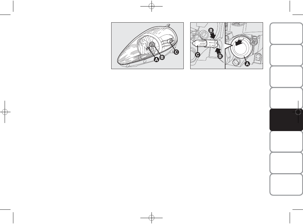
FRONT LIGHT CLUSTERS fig. 16

The front light clusters contain sidelights,
dipped beam, main beam and direction in-
dicator bulbs.

The bulbs are arranged inside the light
cluster as follows:

sidelights

dipped beams/main beams (double light)

direction indicators

SIDELIGHTS fig. 17

To change the bulb, proceed as follows:
❒ remove the snap-fitted rubber cap A,

as shown by the arrow;

❒ press in tabs and remove the bulb

holder;

❒ remove the bulb and replace it;
❒ refit the bulb holder and refit the cap

A, ensuring that it locks into place.

fig. 16

F0M0178m

fig. 17

F0M0179m

-------------------------------------------------------------------------------------------------------------------------------------------------------------

150

SAFETY

ST

AR

TING 

AND DRIVING

W

ARNING

LIGHTS AND MESSAGES

SER

VICE 

AND CARE

TECHNICAL

SPECIFICA

TIONS

INDEX

CONTROLS  AND DEVICES

IN AN

EMERGENCY

DIPPED BEAM / MAIN BEAM
HEADLIGHTS fig. 18

To change the bulb, proceed as follows:
❒ remove the snap-fitted rubber cap A,

as shown by the arrow;

❒ disconnect the central electric connec-

tor and release the bulb holder catch;

❒ remove the bulb and replace it;
❒ fit the new bulb, aligning the outlines of

the metallic part with the grooves on
the reflector;

❒ refit the bulb holder catch and recon-

nect the electrical connector;

❒ refit the cap A, ensuring that it locks in-

to place.

DIRECTION INDICATORS

Front fig. 19/a – 19/b

To change the bulb, proceed as follows:
❒ steer the right/left wheel outwards;
❒ turn the catch A-fig. 19/a as shown by

the arrow, then lift the access flap B;

❒ remove the bulb holder cover C-fig.

19/b by turning it anti-clockwise;

❒ remove the bulb by pushing it in gen-

tly and turning anti-clockwise (“bayo-
net” clamping), then replace it;

❒ refit the bulb holder cover by turning

it clockwise and locking it properly;

❒ close the flap B-fig. 19/a and then turn

the catch A.

fig. 18

F0M0180m

fig. 19/b

F0M0181m

fig. 19/a

F0M0261m

-------------------------------------------------------------------------------------------------------------------------------------------------------------

151

SAFETY

ST

AR

TING 

AND DRIVING

W

ARNING

LIGHTS AND MESSAGES

SER

VICE 

AND CARE

TECHNICAL

SPECIFICA

TIONS

INDEX

CONTROLS  AND DEVICES

IN AN

EMERGENCY

Sidelights fig. 20

To change the bulb, proceed as follows:
❒ slide the lens to press in the inter-

nal catch B, then pull the unit outwards;

❒ turn the bulb holder anti-clockwise,

remove the snap-fitted bulb and re-
place it;

❒ refit the bulb holder into the lens by

turning it clockwise;

❒ refit the unit making sure the internal

catch clicks into place.

FRONT FOG LIGHTS 
(for versions/markets, where provided)

Contact a Fiat Dealership to have bulbs
for the front fog lights A-fig. 21 replaced.

REAR LIGHT CLUSTERS 
fig. 22-23

The rear light clusters contain taillight,
brake light and direction indicator bulbs.

The bulbs are arranged inside the light
cluster as follows:

direction indicators

taillights

taillights/brake light (double light).

fig. 20

F0M0182m

fig. 22

F0M0184m

fig. 21

F0M0223m

-------------------------------------------------------------------------------------------------------------------------------------------------------------

152

SAFETY

ST

AR

TING 

AND DRIVING

W

ARNING

LIGHTS AND MESSAGES

SER

VICE 

AND CARE

TECHNICAL

SPECIFICA

TIONS

INDEX

CONTROLS  AND DEVICES

IN AN

EMERGENCY

To change the bulb proceed as follows:
❒ open the boot then loosen the two fas-

tening screws A;

❒ disconnect the central electric connec-

tor and pull the lens unit outwards;

❒ loosen the screws and remove the

bulb holder;

❒ remove the bulb that needs replacing

Bor by pushing it in slightly and
turning it anti-clockwise (“bayonet”
clamping), then replace it;

❒ refit the bulb holder and tighten the

screws E;

❒ reconnect the electric connector, cor-

rectly realign the unit with the car body
and then tighten the fastening screws A.

REAR FOG LIGHTS fig. 24

Contact a Fiat Dealership to have bulbs
for the rear fog lights replaced.

REVERSE LIGHTS fig. 25

Contact a Fiat Dealership to have bulbs
for the reverse lights replaced.

fig. 24

F0M0208m

fig. 25

F0M0209m

fig. 23

F0M0185m

-------------------------------------------------------------------------------------------------------------------------------------------------------------

153

SAFETY

ST

AR

TING 

AND DRIVING

W

ARNING

LIGHTS AND MESSAGES

SER

VICE 

AND CARE

TECHNICAL

SPECIFICA

TIONS

INDEX

CONTROLS  AND DEVICES

IN AN

EMERGENCY

THIRD BRAKE LIGHT fig. 26-27

To change the bulb proceed as follows:
❒ open the boot;
❒ remove the rubber caps A-fig. 26;
❒ press the catches B-fig. 26 and remove

the lens unit C-fig. 27;

❒ disconnect the electric connector;

❒ press in the tabs D-fig. 27 and remove

the bulb holder;

❒ remove the snap-fitted bulb and replace

it.

NUMBER PLATE LIGHTS 
fig. 28-29

To change the bulb proceed as follows:
❒ manipulate the point shown by the ar-

row and remove the lens unit A-fig. 28;

❒ change the bulb fig. 29 by releasing 

it from the side contacts and making
sure the new bulb is correctly fastened
between these contacts;

❒ reattach the snap-fitted lens unit.

fig. 26

F0M0210m

fig. 27

F0M0211m

fig. 28

F0M0212m

fig. 29

F0M0233m

-------------------------------------------------------------------------------------------------------------------------------------------------------------

154

SAFETY

ST

AR

TING 

AND DRIVING

W

ARNING

LIGHTS AND MESSAGES

SER

VICE 

AND CARE

TECHNICAL

SPECIFICA

TIONS

INDEX

CONTROLS  AND DEVICES

IN AN

EMERGENCY

CHANGING 
AN INTERIOR BULB

For the type of bulb and relevant power
rating, see “Changing a bulb”.

FRONT CEILING LIGHT 
(for versions/markets, where provided)

Proceed as follows to replace the bulbs:
❒ manipulate the points shown by the ar-

rows and remove the light D-fig. 30;

❒ open the protective flap E-fig. 31;
❒ replace bulb F-fig. 33 by releasing it

from the side contacts and making sure
that the new bulb is correctly clamped
between these contacts;

❒ close the protective flap E-fig. 31 and

secure light D-fig. 30 into its housing
making sure that it locks into place. 

FRONT CEILING LIGHT 
WITH SPOT LIGHTS
(for versions/markets, where available)

Proceed as follows to replace the bulbs:
❒ manipulate the points shown by the 

arrows and remove light A-fig. 32;

❒ open the protective flap B;

❒ replace bulbs C-fig. 33 by releasing

them from the side contacts and mak-
ing sure that new bulbs are correctly
clamped between these contacts;

❒ close the lid B-fig. 33 and secure light

A-fig. 32 into its housing making sure
that it locks into place. 

fig. 32

F0M0213m

fig. 33

F0M0234m

fig. 30

F0M0214m

fig. 31

F0M0235m

-------------------------------------------------------------------------------------------------------------------------------------------------------------

155

SAFETY

ST

AR

TING 

AND DRIVING

W

ARNING

LIGHTS AND MESSAGES

SER

VICE 

AND CARE

TECHNICAL

SPECIFICA

TIONS

INDEX

CONTROLS  AND DEVICES

IN AN

EMERGENCY

CHANGING A FUSE

GENERAL INFORMATION

The fuse is a protective device for the
electric system: it comes into action if
there is a fault or improper action on the
system.

Check the state of the corresponding fuse
when a device does not work: the filament
A-fig. 34 must be intact. If it is not, re-
place the blown fuse with a new one of the
same amperage (same colour).

undamaged fuse fig. 34

fuse with damaged filament fig. 34.

fig. 34

F0M0236m

Do not replace one fuse with
another of greater amper-

age; FIRE HAZARD.

WARNING

Never replace a damaged fuse
with metal wires or other 
recycled material.

If a general protection fuse
(MEGA-FUSE, MIDI-FUSE,

MAXI-FUSE) is activated, contact
a Fiat Dealership. 

WARNING

If the same fuse blows again,
contact a Fiat Dealership.

WARNING

Remove the key from the ig-
nition and switch off or dis-

connect all devices before replacing
a fuse.

WARNING

If a general protection fuse
for safety systems (air bag

system, braking system), power unit
systems (engine system, transmission
system) or steering system is triggered,
contact a Fiat Dealership.

WARNING

-------------------------------------------------------------------------------------------------------------------------------------------------------------

156

SAFETY

ST

AR

TING 

AND DRIVING

W

ARNING

LIGHTS AND MESSAGES

SER

VICE 

AND CARE

TECHNICAL

SPECIFICA

TIONS

INDEX

CONTROLS  AND DEVICES

IN AN

EMERGENCY

ACCESSING THE FUSES

The fuses are grouped in three control
units: on the dashboard, in the engine
compartment and in the left-hand side of
the boot.

Dashboard fusebox fig. 36

To access the dashboard fusebox, loosen
the screws A-fig. 35 and remove the
cover.

fig. 36

F0M0415m

3

4

5

6

7

8

9

10

11

12

13

14

1

2

fig. 35

F0M0016m

-------------------------------------------------------------------------------------------------------------------------------------------------------------

157

SAFETY

ST

AR

TING 

AND DRIVING

W

ARNING

LIGHTS AND MESSAGES

SER

VICE 

AND CARE

TECHNICAL

SPECIFICA

TIONS

INDEX

CONTROLS  AND DEVICES

IN AN

EMERGENCY

Engine compartment fusebox 
fig. 38

To access the fusebox located next to 
the battery, remove the protective cover
fig. 37.

fig. 38

F0M0417m

fig. 37

F0M0416m

-------------------------------------------------------------------------------------------------------------------------------------------------------------

158

SAFETY

ST

AR

TING 

AND DRIVING

W

ARNING

LIGHTS AND MESSAGES

SER

VICE 

AND CARE

TECHNICAL

SPECIFICA

TIONS

INDEX

CONTROLS  AND DEVICES

IN AN

EMERGENCY

Boot fusebox fig. 40

To access the fusebox located in the left
side of the boot, open the appropriate flap
(as shown in fig. 39).

fig. 40

F0M0372m

fig. 39

F0M0246m

-------------------------------------------------------------------------------------------------------------------------------------------------------------

159

SAFETY

ST

AR

TING 

AND DRIVING

W

ARNING

LIGHTS AND MESSAGES

SER

VICE 

AND CARE

TECHNICAL

SPECIFICA

TIONS

INDEX

CONTROLS  AND DEVICES

IN AN

EMERGENCY

1

8

13

2

5

11

4

6

14

7

12

3

10

7,5

7,5

5

5

10

5

20

20

20

20

5

5

7,5

FUSE TABLE

Dashboard fusebox fig. 36

DEVICES

FUSE

AMPS

Right dipped beam headlight

Left dipped beam headlight, corrector, headlamp alignment corrector

INT/A supply for switch coils on engine fusebox 
and switch coils on body computer control unit

Front ceiling light, rear ceiling light (VAN version)

Supply and battery for EOBD diagnostic plug, alarm, sound system, 
Blue&Me control unit

INT supply for instrument panel, switch on brake pedal 
(N.O. contact), third brake light

Door locking/unlocking motors, dead lock activation motors, 
boot unlocking motor

Windscreen/rear window washer pump

Electric window motor on driver-side front door

Electric window motor on passenger-side front door

INT supply for dashboard control lights, mirror movement exterior electrics, 
sunroof control unit, My Port infotelematic system socket

Instrument panel 

INT supply for brake pedal switch (NC contact), clutch pedal switch, 
interior heating unit, Blue&Me control unit, sound system capabilities, 
voltage stabiliser control unit, reverse light on rear bumper, 
water sensor on diesel filter, glow plug heating control unit, airflow meter, 
brake booster sensor, switch coils on engine compartment fusebox

-------------------------------------------------------------------------------------------------------------------------------------------------------------

160

SAFETY

ST

AR

TING 

AND DRIVING

W

ARNING

LIGHTS AND MESSAGES

SER

VICE 

AND CARE

TECHNICAL

SPECIFICA

TIONS

INDEX

CONTROLS  AND DEVICES

IN AN

EMERGENCY

Engine compartment fusebox fig. 38

DEVICES

FUSE

AMPS

Single tone horn 

Left main beam headlight, right main beam headlight

Additional heater 

Air conditioning compressor

Heated rear window

Fuel pump on tank

10

14

15

19

20

21

10

15

30

7,5

30

15

-------------------------------------------------------------------------------------------------------------------------------------------------------------

161

SAFETY

ST

AR

TING 

AND DRIVING

W

ARNING

LIGHTS AND MESSAGES

SER

VICE 

AND CARE

TECHNICAL

SPECIFICA

TIONS

INDEX

CONTROLS  AND DEVICES

IN AN

EMERGENCY

15

7,5

15

5

7,5

30

84

85

86

87

88

DEVICES

FUSE

AMPS

Left fog light, right fog light

Methane system management solenoid valves 

Socket (ready for use)

Passenger compartment socket, cigarette lighter

Battery charge status sensor

De-mister on driver-side wing mirror, de-mister on passenger-side wing mirror

-------------------------------------------------------------------------------------------------------------------------------------------------------------

162

SAFETY

ST

AR

TING 

AND DRIVING

W

ARNING

LIGHTS AND MESSAGES

SER

VICE 

AND CARE

TECHNICAL

SPECIFICA

TIONS

INDEX

CONTROLS  AND DEVICES

IN AN

EMERGENCY

17

14

01

03

04

15

10

16

08

07

05

11

13

09

06

02

20

7,5

20

10

15

20

10

Boot fusebox fig. 44

DEVICES

FUSE

AMPS

Sunroof opening system

Alarm system management control unit

Spare

Spare

Spare

Spare

Electric windows system (motor, control unit) on right-hand door

Spare

Driver’s seat heater control unit

Tow hook system (capability for after-sale fuse assembly)

Boot socket

Electric windows system (motor, control unit) on left-hand door

Spare 

Front passenger seat heater control unit

Spare

Spare

-------------------------------------------------------------------------------------------------------------------------------------------------------------

163

SAFETY

ST

AR

TING 

AND DRIVING

W

ARNING

LIGHTS AND MESSAGES

SER

VICE 

AND CARE

TECHNICAL

SPECIFICA

TIONS

INDEX

CONTROLS  AND DEVICES

IN AN

EMERGENCY

RECHARGING 
THE BATTERY

IMPORTANT The battery recharging pro-
cedure is provided for information pur-
poses only. You are recommended to go
to a Fiat Dealership to have this operation
performed.

We recommend recharging the battery
slowly for approximately 24 hours at low
amperage. Rapid charging with high cur-
rents could damage the battery.

VERSIONS WITHOUT
Start&Stop SYSTEM

Charge the battery as follows:
❒ disconnect battery negative terminal;
❒ connect the charger cables to the bat-

tery terminals, observing the polarity;

❒ turn on the charger;
❒ when you have finished, turn the charg-

er off before disconnecting it from the
battery;

❒ reconnect battery negative terminal.

fig. 41

F0M0518m

VERSIONS WITH Start&Stop
SYSTEM (with dummy pole) 
fig. 41 
(for versions/markets, where provided)

To charge, proceed as follows:
❒ disconnect the quick-release negative

terminal from the negative dummy
pole because the battery negative
pole has a sensor monitoring the
battery conditions, that should never
be disconnected from the negative pole
(unless the battery is replaced);

❒ connect the battery charger positive ca-

ble to the battery positive pole and
the negative cable to the dummy pole
B;

❒ switch on the battery charger. At the

end of the charging process, switch the
charger off before disconnecting it;

❒ after disconnecting the battery charg-

er, reconnect the quick-release nega-
tive terminal to the dummy pole B.

-------------------------------------------------------------------------------------------------------------------------------------------------------------

164

SAFETY

ST

AR

TING 

AND DRIVING

W

ARNING

LIGHTS AND MESSAGES

SER

VICE 

AND CARE

TECHNICAL

SPECIFICA

TIONS

INDEX

CONTROLS  AND DEVICES

IN AN

EMERGENCY

RAISING THE CAR

If the car needs to be lifted, go to a Fiat
Dealership which is equipped with the arm
hoist or workshop lift.

The car should be lifted side-on only, by
putting the ends of the arms or the work-
shop lifting device in the areas shown in
the diagram.

Do not try to recharge a frozen
battery; defrost it first to pre-

vent the risk of explosion. If the bat-
tery was frozen, have it inspected by
specialised personnel before recharg-
ing to check that the internal ele-
ments are not damaged and that the
casing is not cracked, which could
cause poisonous, corrosive gas to leak.

WARNING

fig. 42

F0M0513m

Battery fluid is poisonous
and corrosive: avoid contact

with your skin and eyes. The battery
must be recharged in a ventilated
place away from naked flames or
possible sources of sparks to avoid the
risk of explosion and fire.

WARNING

VERSIONS WITH Start&Stop
SYSTEM fig. 42
(without dummy pole) 
(for versions/markets, where provided)

To charge, proceed as follows:
❒ disconnect the connector (pressing

the button B) from the sensor mon-
itoring the battery conditions, on the
negative pole of the battery;

❒ connect the battery charger positive ca-

ble and the negative cable to the ter-
minal of sensor D, according to figure;

❒ turn on the battery charger. At the end

of the charging process, switch the bat-
tery charger off;

❒ after disconnecting the battery charg-

er, reconnect the connector to the
sensor according to figure.

-------------------------------------------------------------------------------------------------------------------------------------------------------------


Content      ..     8      9      10      11     ..