Fiat Abarth (2018 year). Manual - part 2


  Index      Fiat     Fiat Abarth (2018 year) - manual in english


Search            


Content      ..      1      2      3      ..


Fiat Abarth (2018 year). Manual - part 2


WARNING! (Continued)

• Never leave children alone in a vehicle, or with

access to an unlocked vehicle.

• Allowing children to be in a vehicle unattended is

dangerous for a number of reasons. A child or others
could be seriously or fatally injured. Children
should be warned not to touch the parking brake,
brake pedal or the gear selector.

• Do not leave the key fob in or near the vehicle, or in

a location accessible to children, and do not leave the
ignition of a vehicle equipped with Keyless Enter-
N-Go in the ON/RUN mode. A child could operate
power windows, other controls, or move the vehicle.

• Do not leave children or animals inside parked

vehicles in hot weather. Interior heat build-up may
cause serious injury or death.

CAUTION!

An unlocked car is an invitation. Always remove the
key from the ignition and lock all doors when leaving
the vehicle unattended.

Power Door Locks

A power door lock switch is incorporated into the driver
door handle. Push or pull the handle to lock or unlock the
doors and liftgate. If the driver’s door handle is pushed, a
red lock indicator will show on the driver’s door handle
(indicating locked). When the door is closed, the door will
lock.

NOTE:

To prevent the key from being locked in the vehicle,

the doors will automatically unlock if the driver’s door
handle is pushed when the key is in the ignition.

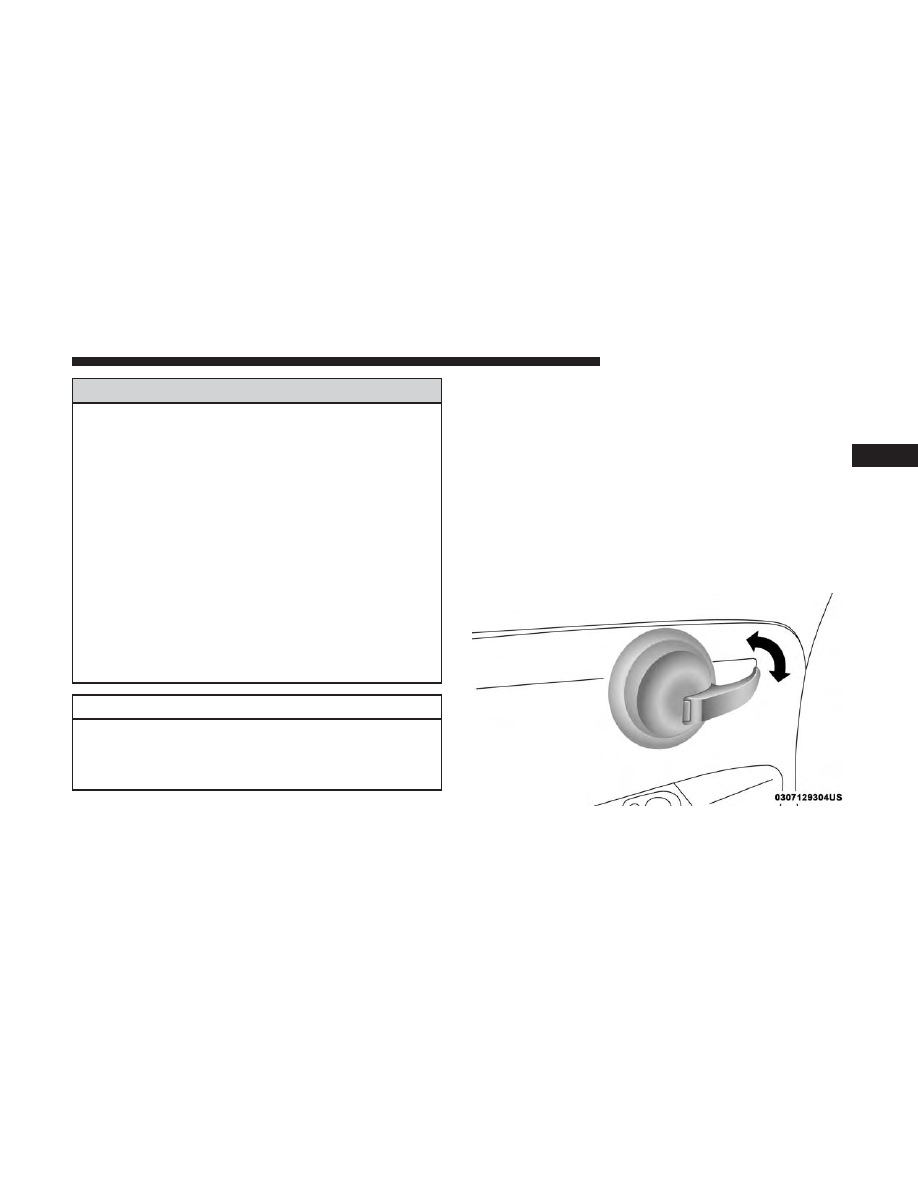
Power Door Lock Handle

3

GETTING TO KNOW YOUR VEHICLE

25

-------------------------------------------------------------------------------------------------------------------------------------------------------------

Auto Door Locks

When enabled, the door locks will lock automatically when
the vehicle’s speed exceeds 12 mph (20 km/h).

NOTE:

Use the Automatic Door Locks feature in accor-

dance with local laws.

Refer to “Uconnect Settings” in “Multimedia” for further
information.

SEATS

Seats are a part of the Occupant Restraint System of the
vehicle.

WARNING!

• It is dangerous to ride in a cargo area, inside or

outside of a vehicle. In a collision, people riding in
these areas are more likely to be seriously injured or
killed.

• Do not allow people to ride in any area of your

vehicle that is not equipped with seats and seat belts.
In a collision, people riding in these areas are more
likely to be seriously injured or killed.

• Be sure everyone in your vehicle is in a seat and

using a seat belt properly.

Manual Adjustment Front Seats

Forward/Rearward Adjustment

The adjusting bar is located at the front of the seats, near
the floor.

Adjusting Bar

26

GETTING TO KNOW YOUR VEHICLE

-------------------------------------------------------------------------------------------------------------------------------------------------------------

While sitting in the seat, lift up on the bar and move the
seat forward or rearward. Release the bar once the desired
position is reached. Then, using body pressure, move
forward and rearward on the seat to be sure that the seat
adjusters have latched.

WARNING!

• Adjusting a seat while driving may be dangerous.

Moving a seat while driving could result in loss of
control which could cause a collision and serious
injury or death.

• Seats should be adjusted before fastening the seat

belts and while the vehicle is parked. Serious injury
or death could result from a poorly adjusted seat belt.

Seat Height Adjustment

The driver’s seat height can be raised or lowered by using
a lever, located on the outboard side of the seat. Pump the
lever upward to raise the seat height, or pump the lever
downward to lower the seat height.

Height Adjuster

3

GETTING TO KNOW YOUR VEHICLE

27

-------------------------------------------------------------------------------------------------------------------------------------------------------------

Recline Adjustment
The recline adjustment lever is located on the inboard side
of the seat. To recline the seatback, lift up the recline lever,
lean back until the desired position has been reached, and
release the lever.

WARNING!

Do not ride with the seatback reclined so that the
shoulder belt is no longer resting against your chest. In
a collision you could slide under the seat belt, which
could result in serious injury or death.

EZ Entry Feature

The driver and front passenger seats have an EZ entry
feature for rear seat passengers. Pull upward on the release
tether, located on the outboard side of the seatback, dump
the seatback forward, then slide the seat forward to allow
access in and out of the rear seat.

Lift the seatback upright and push the seat rearward to its
locked position once the rear passengers are seated.

Recline Lever

EZ Entry Pull Strap

28

GETTING TO KNOW YOUR VEHICLE

-------------------------------------------------------------------------------------------------------------------------------------------------------------

Memory Seat Feature

Both front seats have a memory feature, which can operate
in two ways:
• Memory Function Option 1 (Full Seat Back And Track

Fore/Aft Position Memory) — After using the EZ entry
function, the seatback angle and the track fore/aft
adjuster can both re-lock into the position they were
most recently adjusted to. This is accomplished if the
seat is moved fully rearward to its last fore/aft position
on the tracks before the seat back is returned upright.

• Memory Function Option 2 (Seat Back Only Memory) —

After using the EZ entry function, the seat back may first
be returned upright prior to going back to the last fore/aft
(memory) position on the tracks. This results in the seat
back memory being set only – The track will then be
locked forward of its last set fore/aft memory position. To
then reset the fore/aft track memory feature (to reestab-
lish Memory Function Option 1), the seat has to be
returned fully rearward to its last fore/aft memory track
position as described in Memory Function Option 1.

Heated Seats — If Equipped

On some models, the front driver and passenger seats may
be equipped with heaters in both the seat cushions and
seatbacks. The controls for the front heated seats are
located on the center instrument panel area.

Push the switch once to turn on the heated seats.
Push the switch a second time to shut the heating
elements off.

NOTE:

Once a heat setting is selected, heat will be felt

within two to five minutes.

WARNING!

• Persons who are unable to feel pain to the skin

because of advanced age, chronic illness, diabetes,
spinal cord injury, medication, alcohol use, exhaus-
tion or other physical condition must exercise care
when using the seat heater. It may cause burns even
at low temperatures, especially if used for long
periods of time.

(Continued)

3

GETTING TO KNOW YOUR VEHICLE

29

-------------------------------------------------------------------------------------------------------------------------------------------------------------

WARNING! (Continued)

• Do not place anything on the seat or seatback that

insulates against heat, such as a blanket or cushion.
This may cause the seat heater to overheat. Sitting in
a seat that has been overheated could cause serious
burns due to the increased surface temperature of the
seat.

Manual Folding Rear Seat

The rear seatbacks have a fold down feature to allow
increased cargo capacity.

Push down the release button, located at the outboard top
of the seatback and move the seatback to its folded-down
position to provide a flat load floor cargo area. When
returning the seatback to its upright position, push rear-
ward until the seatback is properly latched.

Rear Seat Release Buttons

30

GETTING TO KNOW YOUR VEHICLE

-------------------------------------------------------------------------------------------------------------------------------------------------------------

WARNING!

Do not pile luggage or cargo higher than the top of the
seatback. This could impair visibility or become a
dangerous projectile in a sudden stop or collision.

HEAD RESTRAINTS

WARNING!

• All occupants, including the driver, should not oper-

ate a vehicle or sit in a vehicle’s seat until the head
restraints are placed in their proper positions in
order to minimize the risk of neck injury in the event
of a crash.

• Be certain that the seatback is securely locked into

position. If the seatback is not securely locked into
position the seat will not provide the proper stability
for child seats and/or passengers. An improperly
latched seat could cause serious injury.

Folded Rear Seats

3

GETTING TO KNOW YOUR VEHICLE

31

-------------------------------------------------------------------------------------------------------------------------------------------------------------

Front Non-Adjustable Head Restraints

The non-adjustable head restraints are form fitted into the
upper structure of the seatback and are designed to reduce
the risk of injury by restricting head movement in the event
of a rear impact. The seatback should be properly adjusted
to an upright position where the head restraint is posi-
tioned as close as possible to the back of your head.

WARNING!

Be certain that the seatback is securely locked into
position. If the seatback is not securely locked into
position the seat will not provide the proper stability
for child seats and/or passengers. An improperly
latched seat could cause serious injury.

Rear Head Restraints

To raise the head restraint, pull upward on the head
restraint. To lower the head restraint, push the adjustment
button, located at the base of the head restraint, and push
downward on the head restraint. Refer to “Occupant
Restraints” in “Safety” for information on tether routing.

NOTE:

To remove the head restraint, raise it as far as it can

go then push the release button and the adjustment button
at the base of each post while pulling the head restraint up.
To reinstall the head restraint, put the head restraint posts
into the holes and push downward. Then adjust the head
restraint to the appropriate height.

Non-Adjustable Head Restraint

32

GETTING TO KNOW YOUR VEHICLE

-------------------------------------------------------------------------------------------------------------------------------------------------------------

WARNING!

ALL the head restraints MUST be reinstalled in the
vehicle to properly protect the occupants. Follow the
re-installation instructions above prior to operating the
vehicle or occupying a seat.

STEERING WHEEL

Tilt Steering Column — If Equipped

This feature allows you to tilt the steering column upward
or downward. The tilt control lever is located on the
left-side of the steering column, below the turn signal
controls.

Push down on the lever to unlock the column. With one
hand firmly on the steering wheel, move the steering
column up or down as desired. Push the lever up to lock
the column firmly in place.

Head Restraint

1 — Release Button
2 — Adjustment Button

Tilt Control Lever

3

GETTING TO KNOW YOUR VEHICLE

33

-------------------------------------------------------------------------------------------------------------------------------------------------------------

WARNING!

Do not adjust the steering column while driving.
Adjusting the steering column while driving or driv-
ing with the steering column unlocked, could cause the
driver to lose control of the vehicle. Failure to follow
this warning may result in serious injury or death.

MIRRORS

Inside Day/Night Mirror

The mirror can be adjusted up, down, left, and right for
various drivers. The mirror should be adjusted to center on
the view through the rear window.

Headlight glare from vehicles behind you can be reduced
by moving the small control under the mirror to the night
position (toward the rear of the vehicle). The mirror should
be adjusted while set in the day position (toward the
windshield).

Automatic Dimming Mirror — If Equipped

This mirror automatically adjusts for headlight glare from
vehicles behind you. You can turn the feature on or off by
pushing the button at the base of the mirror. The on/off
symbol on the button will illuminate when the auto-
dimming feature is enabled.

NOTE:

This feature is disabled when the vehicle is mov-

ing in REVERSE.

Adjusting Rearview Mirror

34

GETTING TO KNOW YOUR VEHICLE

-------------------------------------------------------------------------------------------------------------------------------------------------------------

CAUTION!

To avoid damage to the mirror during cleaning, never
spray any cleaning solution directly onto the mirror.
Apply the solution onto a clean cloth and wipe the
mirror clean.

Power Mirrors

The power mirror controls are located on the driver’s door
trim panel.

The power mirror controls consist of a mirror select switch
and a four-way mirror control switch. To adjust a mirror,
push the mirror select switch to either the L (left) or R
(right) to select the mirror you need to adjust.

Using the mirror control switch, push on any of the four
arrows for the direction that you want the mirror to move.

Automatic Dimming Mirror Power Button

Power Mirror Switches

3

GETTING TO KNOW YOUR VEHICLE

35

-------------------------------------------------------------------------------------------------------------------------------------------------------------

WARNING!

Vehicles and other objects seen in the passenger side
convex mirror will look smaller and farther away than
they really are. Relying too much on your passenger
side convex mirror could cause you to collide with
another vehicle or other object. Use your inside mirror
when judging the size or distance of a vehicle seen in
the passenger side convex mirror.

Folding Mirrors

The exterior mirrors are hinged to allow the mirror to pivot
forward or rearward to help avoid damage. The mirror has
three detent positions: full forward, normal and full rear-
ward.

Spotter Mirror — If Equipped

Some models are equipped with a driver’s side spotter
mirror. The spotter mirror allows for a greater range of
visibility on the driver’s side of the vehicle.

Heated Mirrors — If Equipped

These mirrors are heated to melt frost or ice. This
feature will be activated whenever you turn on the

rear window defroster (if equipped). Refer to “Climate
Controls” in “Getting To Know Your Vehicle” for further
information.

Spotter Mirror

36

GETTING TO KNOW YOUR VEHICLE

-------------------------------------------------------------------------------------------------------------------------------------------------------------

EXTERIOR LIGHTS

Multifunction Lever

The multifunction lever, located on the left side of the
steering wheel, controls the operation of the headlights,
headlight beam selection, passing light and turn signals.

NOTE:

The headlights can only be turned on with the

ignition in the ON/RUN position.

Headlights

Rotate the end of the multifunction lever upward
to the first detent for headlight operation.

NOTE:

When the headlights are turned on, the Daytime

Running Lights will be deactivated.

Daytime Running Lights

To activate the Daytime Running Lights (DRL), rotate the
end of the multifunction lever to the symbol.

NOTE:

The low beams and side/taillights will not be on

with DRL.

Headlight Operation

3

GETTING TO KNOW YOUR VEHICLE

37

-------------------------------------------------------------------------------------------------------------------------------------------------------------

If allowed by law in the country in which the vehicle was
purchased the DRL function can be turned on or off using
the display menus. Refer to “Uconnect Settings” in “Mul-
timedia” for further information.

High Beams

With the low beams activated, push the multifunc-
tion lever towards the instrument panel to turn on

the high beams. Pull the multifunction lever toward the
steering wheel to turn off the high beams.

Flash-To-Pass

You can signal another vehicle with your headlights by
partially pulling the multifunction lever toward the steer-
ing wheel. This will cause the high beam headlights to turn
on until the lever is released.

Parking Lights

To turn on the parking lights, remove the key or
turn the ignition to OFF/LOCK position and
turn on the headlights.

Follow Me Home/Headlight Delay

When this feature is selected, the driver can choose to have
the headlights remain on for a preset period of time.

Activation

Remove the key or turn the ignition to the STOP (OFF/
LOCK) position, and pull the multifunction lever toward
the steering wheel within two minutes. Each time the lever
is pulled, the activation of the lights will be extended by 30
seconds. The activation of the lights can be extended to a
maximum of 210 seconds.

Deactivation

Pull the multifunction lever toward the steering wheel and
hold it for more than two seconds.

Fog Lights — If Equipped

The fog light switch is located on the center stack of the
instrument panel, just below the radio.

38

GETTING TO KNOW YOUR VEHICLE

-------------------------------------------------------------------------------------------------------------------------------------------------------------

Push the switch once to turn the front fog lights on. Push
the switch a second time to turn the front fog lights off.

Turn Signals

Push the multifunction lever upward to signal a right turn
or downward to signal a left turn. The corresponding
indicator in the instrument cluster display will blink to
indicate the operation of the turn signal.

NOTE:

The indicators will automatically turn off when the

turn has been completed and the steering wheel is returned
to a straight position.

Lane Change Assist

Tap the lever up or down once, without moving beyond
the detent, and the turn signal (right or left) will flash three
times. Then, the turn signal (right or left) will automatically
turn off.

Fog Light Switch

Turn Signal Operation

3

GETTING TO KNOW YOUR VEHICLE

39

-------------------------------------------------------------------------------------------------------------------------------------------------------------

INTERIOR LIGHTS

The interior light switches are located in the overhead
console. The interior lights can be set to three different
positions (Off/Left Position, Center Position, On/Right
Position).

Using the switch on the left overhead, push the switch to
the right from its center position and the lights are always
on. Push the switch to the left from its center position and
the lights are always off. Leave the switch in the center
position, and the lights are turned on and off when the
doors are opened or closed. The switch on the right side of
the overhead console controls the map or reading function
of the lights. Push the switch to the right to turn on the
right light and push the switch to the left to turn on the left
light.

CAUTION!

Before getting out of the vehicle be sure that the switch
is in the center position or that the lights are off to
avoid draining the battery.

Interior Light Timing (Center Position)

There are four different modes of operation that can be
activated in this position:
• When one door is opened, a three minute timer is

activated.

• When the key is removed from the ignition (within two

minutes of the ignition being turned OFF), a 10 second
timer is activated.

• When the doors are unlocked with the key fob, a 10

second timer is activated.

• When the doors are locked with the key fob, the lights

will turn off.

Interior Light Timing (On/Right Position)

When all doors are closed a 15-minute timer is activated.

NOTE:

The timer is deactivated when the key is moved

into the ON/RUN position.

40

GETTING TO KNOW YOUR VEHICLE

-------------------------------------------------------------------------------------------------------------------------------------------------------------


Content      ..      1      2      3      ..