Dongfeng DFA1063DJ10 (14)-301/303. Manual - part 9
 

  Index      Dongfeng     Dongfeng DFA1063DJ10 (14)-301/303 - service manual 2006 year


Search            


Content   ..  7  8  9  10   ..


Dongfeng DFA1063DJ10 (14)-301/303. Manual - part 9


Transmission

MT-11

Assembly Point

Countershaft assembly

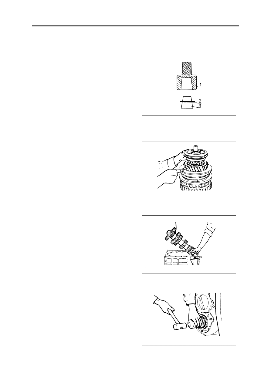
Press on gear and spacer according to the counter

procedure of disassembly, assemble snap ring with sim-
ple taper tool.

Note: Before press on gear, the gear key groove

must align with key on the shaft to avoid damaging.
Make sure that the axial clearances of each gear
correspond to standard axial clearance.

(1)Upper taper sleeve

(2)Snap ring

(3)Down taper sleeve

Mainshaft assembly

Assemble each gear synchronizer from front and

rear end according to the counter procedure of disassem-
bly.

Note: when assemble 2nd and 3rd  synchronizer;

make sure that the bulging part of sliding sleeve face
forward.

Make sure that the axial clearances of each gear

correspond to standard axial clearance.

Sub assembly assemble

1.Mount the countershaft assembly into countershaft hole

of transmission assembly in correct direction.

2.Align the countershaft at countershaft front bearing

hole of front end of casing, cover the front bearing, tap
the bearing outer ring regularly with copper rod until
the bearing get close to axle journal pedestal sit, cover
the rear bearing from body rear end, tap the bearing
outer ring regularly with copper rod until the bearing
get close to axle journal pedestal sit, cover the lock
plate, tighten the locking nut with the tightening torque
of 146Nm, turn over the lock plate to lock the nut, put
on the snap ring at the bearing outer ring.

Transmission

MT-12

3.Put the needle bearing and spacer into reverse speed

gear inner hole, put the reverse speed gear through the
reverse speed gear inspecting hole, insert the reverse
speed gear shaft from the transmission casing rear end,
seize the lock plate with the bolt to fix it.

4.Put the main shaft into casing, cover the rear bearing

from mainshaft rear end, tap the bearing with copper
rod to make the bearing get close the shoulder of main-
shaft spline, cover the drive gear of speedometer and
spacer, then put the snap ring at bearing outer ring.

5.Press the rear bearing into input shaft, assemble the

snap ring and the steel ring of bearing outer ring, put
the mainshaft front bearing into inner hole.

6.Put the input shaft into casing front end bearing hole,

align the mainshaft front end axle journal with the
front bearing hole, tap the input shaft rear bearing
slightly with copper rod, rotate the input shaft with
had, put the bearing into casing seating hole smoothly.

Transmission

MT-13

7.Put the sealing gasket with sealing glue form input

shaft front end to the positing place of bearing cover,
cover the bearing cap and tighten it with bolt.

Note: Install the clutch release sleeve return spring

bracket at the upper left bolt or the bearing cap.

8.Install each sealing gasket with sealing glue onto coun-

tershaft front and rear bearing cap, power-take-off
cover, reverse speed inspecting hole cover and main-
shaft rear bearing cap, tighten them with bolts.

Note: Spread or sealing glue at the thread of bolt.

9.Install oil ring, fix the parking brake assembly onto

mainshaft rear bearing cap, then cover the parking
brake flange onto mainshaft, install disk like washer,
tighten the locking nut.

Tightening torque              196~245Nm

Assemble of the assembly

Before assemble transmission onto truck, make sure that the corresponding parts is tightened.

1.Install transmission and bracket as a assembly into truck with transmission jack and steel wire, make sure that

input key into clutch driven disc hub spline.

2.Install clutch booster or clutch slave cylinder, return spring and dowel pin. Adjust free running for clutch outer

pull rod.

Free running for clutch outer pull rod                2~3mm

3.Install transmission operating tie rod.

4.Install propeller shaft and central supporter.

Propeller shaft tightening torque                 215~245Nm

Central supporter tightening torque             160~220Nm

5.Connect all the circuits and pipe lines.

6.Made sure that drain plug screw is tightened, and gear oil, then tighten plug screw of oil filler.

Tightening torque                    120~140Nm

Transmission

MT-14

Transmission Control System

General Construction

Transmission control mechanism

1.Gear shift konb assy
2.shift lever assy
3.Shift rocker shaft
4.Selector rocker shaft
5.Bushing
6.Selector rocker and shift sleeve sets
7.Sheathing
8.Selector return spring
9.Buffer shell
10.Flexible shaft and rocker shaft bracket sets

11.Shift and selector flexible shaft with ball joint 
assy
12.Flexible shaft clip board
13.Upper bracket, double hose clip
14.Shift, selector flrxible shaft clip board
15.Flexible shaft bracket assy
16.Pin 
17.Selector rocker
18.Pin needle, bushing


Content   ..  7  8  9  10   ..