MINI Clubman (2021 year). Manual in english - page 3

Opening and closing
CONTROLS
Exporting is helpful when storing and re-
System limits
trieving personal settings, for instance be-
A clear assignment between the vehicle key
fore delivering the vehicle to a workshop.
and driver may not be possible in the fol-
The stored driver profiles can be taken into
lowing cases, for example.
another vehicle.
- The passenger unlocks the vehicle with
Via the Central Information Display (CID):
his or her own vehicle key, but another
1.
"My MINI"
person is driving.
- The driver unlocks the vehicle via Com-
2. "Driver profiles"
fort Access and has multiple vehicle
3. Select driver profile.
keys with him or her.
The driver profile marked with this
- The driver changes, but the vehicle is
symbol can be exported.
not locked and unlocked.
4. "Export driver profile (USB)"
- Multiple vehicle keys are located out-
Select USB storage device as needed.
side of the vehicle.
Importing driver profiles
Profiles stored on a USB storage device can
Adjusting
be imported via the USB port.
The existing settings of the active driver
General information
profile are overwritten with the settings of
Depending on the package and country ver-
the imported driver profile.
sion, various settings are available for the
Via the Central Information Display (CID):
vehicle key functions.
1.
"My MINI"
These settings are stored for the driver pro-
file, refer to page 71, currently used.
2. "Driver profiles"
3. Select the driver profile to overwrite.
Unlocking
The driver profile marked with this
symbol can be overwritten.
Doors
4. "Import driver profile (USB)"
Via the Central Information Display (CID):
Select USB storage device as needed.
1.
"My MINI"
5. Select the driver profile to be imported.
2. "Vehicle settings"
3. "Doors/Key"
Displaying driver profiles during start
The driver profiles can be displayed at each
4. "Driver's door" or "All doors"
startup to select the desired profile.
5. Select the desired setting:
Via the Central Information Display (CID):
- "Driver's door only"
1.
"My MINI"
Only the driver's door and the fuel
filler flap are unlocked. Pressing
2. "Driver profiles"
again unlocks the entire vehicle.
3. "Show driver profiles at startup"
- "All doors"
The entire vehicle is unlocked.
73

CONTROLS
Opening and closing
Split doors
The most recent position is independent of
the positions saved via the seat memory.
Via the Central Information Display (CID):
1.
"My MINI"
Automatic locking
2.
"Vehicle settings"
Via the Central Information Display (CID):
3.
"Doors/Key"
1.
"My MINI"
4.
2. "Vehicle settings"
The text next to the symbol indicates
3. "Doors/Key"
the current setting.
4. Select the desired setting:
5.
Select the desired setting:
- "Lock automatically"
- "Split Rear Doors"
The vehicle locks automatically after
Only the split doors are opened.
a while if no door is opened after un-
- "Split Rear Doors and door(s)"
locking.
The split doors are opened and the
- "Lock after starting to drive"
doors unlocked.
The vehicle locks automatically after
- "Split doors open only when the
you drive off.
vehicle has first been unlocked"
The vehicle must be unlocked before
Automatic unlocking
the split doors can be used with the
Via the Central Information Display (CID):
vehicle key.
1.
"My MINI"
- "Button lock"
It is not possible to use the split
2. "Vehicle settings"
doors via the vehicle key.
3. "Doors/Key"
Depending on the vehicle equipment and
4. "Unlock at end of trip"
country version, this setting may not be of-
After the engine is switched off by
fered.
pressing the Start/Stop button, the
locked vehicle is automatically un-
Adjusting the last seat and mirror
locked.
position
Via the Central Information Display (CID):
Confirmation signals from the
1.
"My MINI"
vehicle
Via the Central Information Display (CID):
2. "Driver profiles"
3. Select driver profile.
1.
"My MINI"
The setting can be made for the
2. "Vehicle settings"
driver profile marked with this symbol.
3. "Doors/Key"
4. "Last seat position automatic"
4. Deactivate or activate the desired con-
When the vehicle is unlocked, the driver's
firmation signals.
seat and exterior mirrors resume their last
- "Flash for lock/unlock"
set positions.
74
Opening and closing
CONTROLS
Unlocking is signaled by two flashes,
Overview
locking by one.
- With alarm system:
"Acoustic signal for lock/unlock"
Unlocking is signaled by one honk of
the horn.
Alarm system
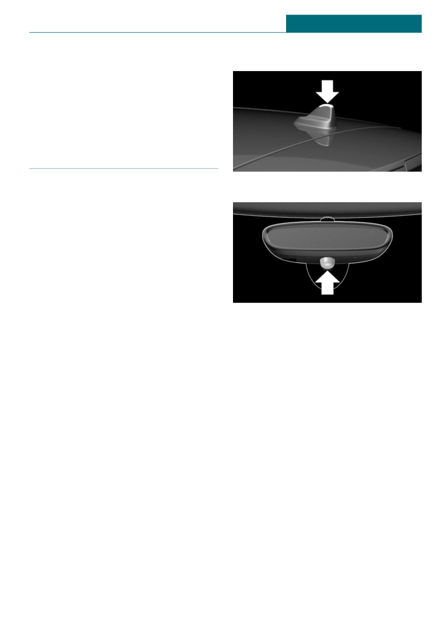
Indicator light in the roof fin.
General information
When the vehicle is locked, the vehicle
alarm system reacts to the following
changes:
- Unauthorized opening of a door, the
hood or the split doors.
- Movements in the car's interior.
- Changes in the vehicle tilt, for instance,
during attempts at stealing a wheel or
when towing the vehicle.
Indicator light on the interior mirror.
- Disconnected battery voltage.
- Improper use of the socket for Onboard
Diagnosis.
Switching on/off
- Locking the vehicle while a device is
The alarm system is switched on or off as
connected to the socket for the OBD On-
soon as the vehicle is locked with the vehi-
board-Diagnosis. For socket for the OBD
cle key or unlocked or locked via Comfort
Onboard Diagnosis, refer to page 271.
Access.
The alarm system signals these changes vis-
ually and acoustically:
Opening the doors with the alarm
- Acoustic alarm:
system switched on
Depending on local regulations, the
The alarm system is triggered when a door
acoustic alarm may be suppressed.
is opened if the door was unlocked using
the integrated key in the door lock.
- Visual alarm:
Switching off the alarm, refer to page 76.
By flashing of the hazard warning sys-
tem and headlights, where required.
Opening the split doors with the
Do not modify the system to ensure func-
alarm system switched on
tion of the alarm system.
The split doors can be opened even when
the alarm system is switched on.
After the split doors are closed, they are
locked and monitored again when the doors
75
CONTROLS
Opening and closing
are locked. The hazard warning system
Interior motion sensor
flashes once.
The windows and the glass sunroof must be
closed for the system to function properly.
Panic mode
You can trigger the alarm system if you find
Avoiding unintentional alarms
yourself in a dangerous situation.
- Press the button on the vehicle
General information
key and hold for at least 3 sec-
The tilt alarm sensor and interior motion
onds.
sensor can trigger an alarm, although no un-
- Briefly press the button on the vehicle
authorized action occurred.
key three times in succession.
Possible situations for an unwanted alarm:
- In automatic vehicle washes.
To switch off the alarm: press any button.
- In duplex garages.
Signals of the indicator lights
- During transport on trains carrying ve-
hicles, at sea or on a trailer.
-
The indicator light flashes briefly every
2 seconds:
- With animals in the vehicle.
The alarm system is switched on.
- When the vehicle is locked after start of
fueling.
-
Indicator light flashes for approx.
10 seconds, then it flashes briefly every
The tilt alarm sensor and the interior mo-
2 seconds:
tion sensor can be switched off in such sit-
uations.
Interior motion sensor and tilt alarm
sensor are not active, as doors, hood, or
split doors are not correctly closed. Cor-
Switching off the tilt alarm sensor and
rectly closed access points are secured.
interior motion sensor
When the still open access points are
Press the button on the vehicle key
closed, the interior motion sensor and
within 10 seconds as soon as the
tilt alarm sensor will be switched on.
vehicle is locked.
-
The indicator light goes out after un-
The indicator light lights up for approx.
locking:
2 seconds and then continues to flash.
The vehicle has not been tampered with.
The tilt alarm sensor and interior motion
-
The indicator light flashes after unlock-
sensor are switched off until the vehicle is
ing until the engine ignition is switched
locked again.
on, but no longer than approx. 5 mi-
nutes:
Switching off the alarm
An alarm has been triggered.
- Unlock the vehicle with the vehicle key.
- Unlock the vehicle with the integrated
Tilt alarm sensor
key and switch on the ignition using the
The tilt of the vehicle is monitored.
emergency detection of the vehicle key,
The alarm system responds in situations
refer to page 63.
such as attempts to steal a wheel or when
- With Comfort Access: if you have the
the vehicle is towed.
vehicle key with you, unlock the vehicle
76
Opening and closing
CONTROLS
using the button on the driver's side or
The window opens while the switch is
passenger side door.
being held.
-
Press the switch beyond the resist-
ance point.
Power windows
The window opens automatically. Press-
ing the switch again stops the motion.
General information
Convenient opening with the vehicle key,
If an accident of a certain severity occurs,
refer to page 61.
the windows are automatically closed ex-
cept a gap.
Closing
Safety information
-
Pull the switch to the resistance
point.
Warning
The window closes while the switch is
When operating the windows, body parts
being held.
and objects can be jammed. There is a risk
of injury or risk of damage to property.
-
Pull the switch beyond the resist-
Make sure that the area of movement of
ance point.
the windows is clear during opening and
The window closes automatically if the
closing.
door is closed. Pulling the switch again
stops the motion.
Convenient closing with the vehicle key, re-
Overview
fer to page 62.
Closing via Comfort Access, refer to
page 67.
Jam protection system
Concept
The jam protection prevents objects or body
parts becoming jammed between the door
frame and window while a window is being
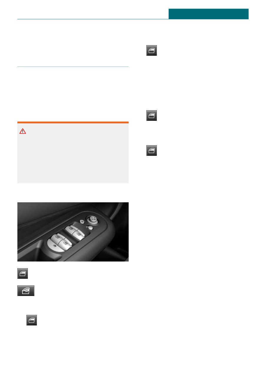
Power windows.
closed.
General information
Safety switch.
If resistance or a blockage is detected while
a window is being closed, the closing action
is interrupted.
Opening
The window opens slightly.
-
Press the switch to the resistance
point.
77
CONTROLS
Opening and closing
Safety information
The LED lights up if the safety function is
switched on.
Warning
Malfunction
Accessories on the windows such as an-
tennas can impact jam protection. There is
a risk of injury. Do not install accessories
General information
in the area of movement of the windows.
In certain situations a window can only be
operated to a limited extent.
- After a power failure during the opening
Closing without the jam protection
or closing process, the a window can
system
only be operated to a limited extent. The
In case of danger from the outside or if ice
system must be initialized in this case.
might prevent normal closing, proceed as
- The power window motors are equipped
follows:
with overheating protection. If a win-
dow is opened and closed several times
1.
Pull the switch past the resistance
within a short period of time, the over-
point and hold it there.
heating protection switches the motor
The window closes with limited jam pro-
off temporarily. Depending on the de-
tection. If the closing force exceeds a
gree of overheating, it may only be pos-
specific threshold, closing is inter-
sible to close the window or it may not
rupted.
be possible to operate it at all.
In this case: allow the power window
2.
Pull the switch past the resistance
motor to cool down.
point again within approx. 4 seconds
and hold it there.
Initializing the system
The window closes without jam protec-
The system can be initialized when the ve-
tion.
hicle is stationary and the engine is run-
ning.
Safety switch
During initialization, the affected window
closes without jam protection.
General information
The safety switch can be used to prevent
Warning
children, for instance from opening and
closing the rear windows using the
When operating the windows, body parts
switches in the rear.
and objects can be jammed. There is a risk
of injury or risk of damage to property.
If an accident of a certain severity occurs,
Make sure that the area of movement of
the safety function is switched off automati-
the windows is clear during opening and
cally.
closing.
Switching on/off
1. Open the affected window completely.
Press the button.
2.
Pull the switch to the resistance
point and hold.
78
Opening and closing
CONTROLS
The window closes.
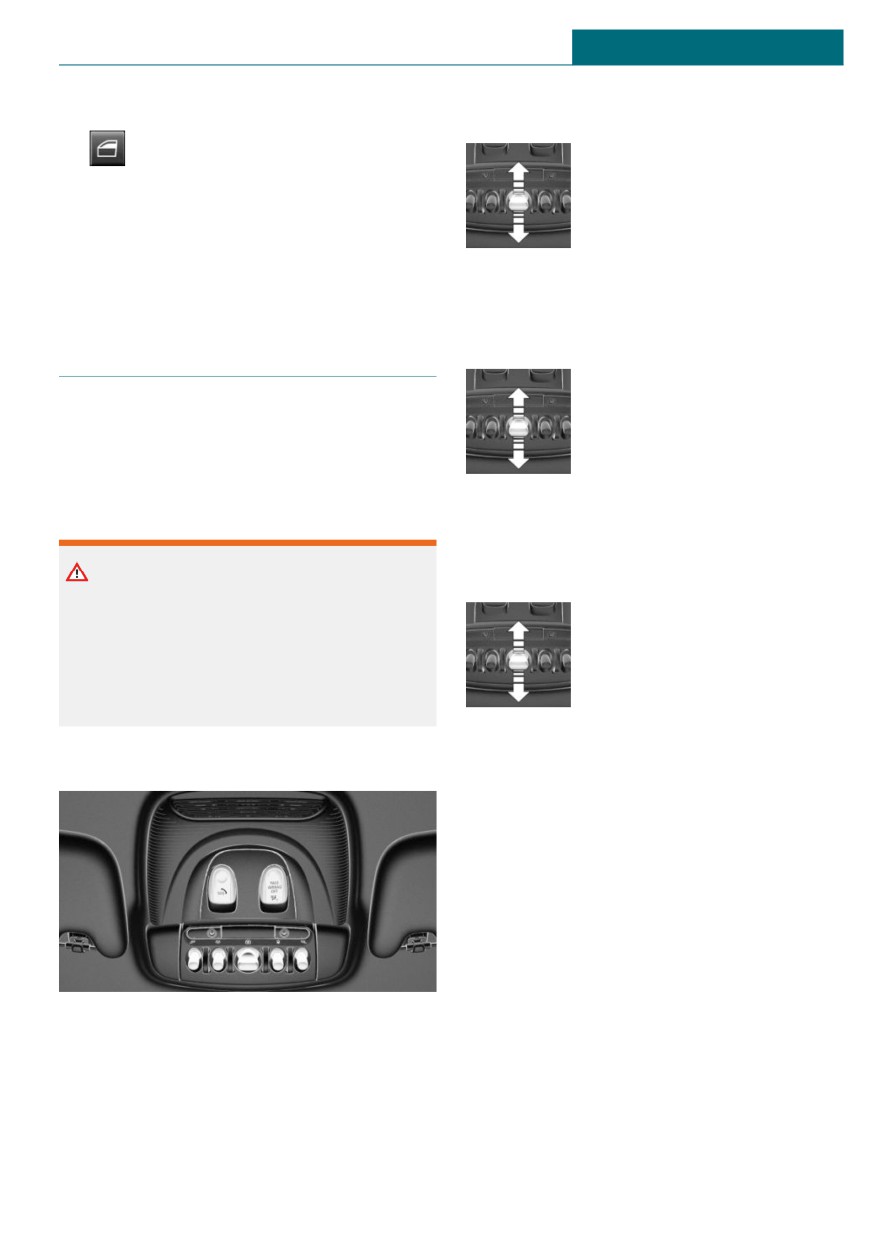
Tilting the glass sunroof
Press back the switch up to or
3.
Continue holding the switch pulled
beyond the resistance point
to the resistance point.
and release it.
The window opens and closes once or
The glass sunroof is raised.
twice after approx. 15 seconds, depend-
ing on the vehicle's equipment.
4. Release switch.
Opening glass sunroof
When the glass sunroof is closed
Panoramic glass sunroof
Press the switch back beyond
the resistance point and re-
General information
lease it twice.
In the event of a severe accident, the glass
The glass sunroof is opened.
sunroof is automatically closed.
Pressing the switch again
stops the motion.
Safety information
With the glass sunroof completely
Warning
raised
Body parts can be jammed when operating
- Slide switch back to the re-
the glass sunroof. There is a risk of injury.
sistance point and hold.
Make sure that the area of movement of
The glass sunroof is
the glass sunroof is clear during opening
opened as long as the
and closing.
switch is pressed.
- Press the switch back beyond the resist-
Overview
ance point and release it.
The glass sunroof is opened.
Pressing the switch again stops the mo-
tion.
Comfort position
In some models, the wind noises in the car's
interior are lowest when the glass sunroof
is not fully open. In these models, the auto-
matic function initially only opens the glass
sunroof up to this comfort position.
Pressing the switch again opens the glass
sunroof fully.
79
CONTROLS
Opening and closing
Closing glass sunroof
Closing without the jam protection
system
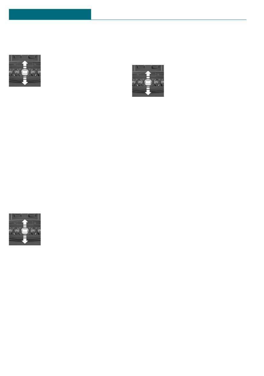
With the glass sunroof open
If there is an external danger, proceed as
- Slide switch forward to the
follows:
resistance point and hold.
The glass sunroof is closed
as long as the switch is
pressed and stops in the
raised position.
- Press the switch forward beyond the re-
1. Push the switch forward past the resist-
sistance point and release it.
ance point and hold it.
The glass sunroof is closed and stops in
The glass sunroof closes with limited
the raised position.
jam protection. If the closing force ex-
Pressing the switch again stops the mo-
ceeds a specific threshold, closing is in-
tion.
terrupted.
- Press the switch forward beyond the re-
2. Push the switch forward again past the
sistance point and release it twice.
resistance point and hold until the glass
sunroof closes without jam protection.
The glass sunroof is closed.
Make sure that the closing area is clear.
Pressing the switch again stops the mo-
tion.
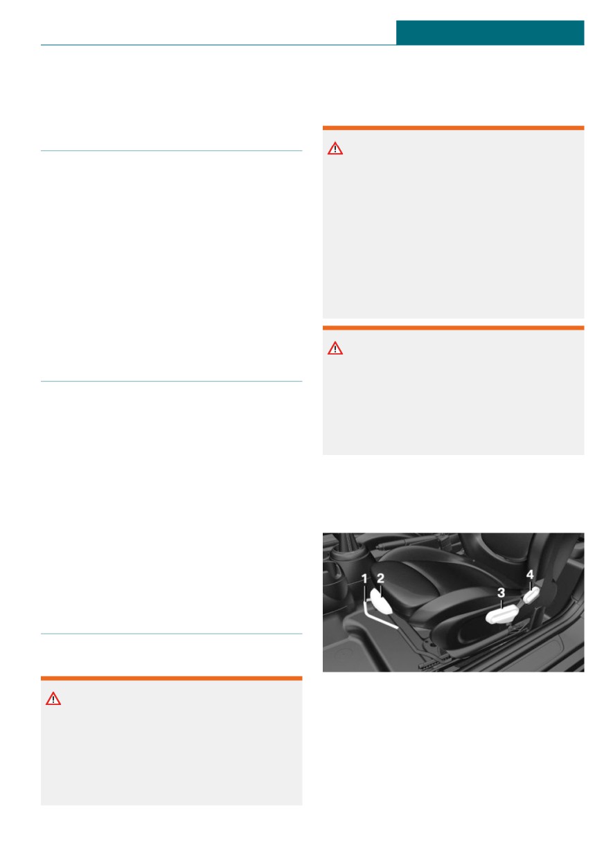
Initializing after a power
interruption
With the glass sunroof completely
raised
After a power failure during the opening or
closing process, the glass sunroof can only
Press the switch forward be-
be operated to a limited extent. The system
yond the resistance point and
must be initialized in this case. MINI rec-
release it.
ommends having this work performed only
The glass sunroof is closed.
by a dealer's service center or another quali-
fied service center or repair shop.
Jam protection system
Concept
The jam protection prevents objects or body
parts from becoming jammed between the
roof and glass sunroof while the glass sun-
roof is closing.
General information
If resistance or a blockage is detected while
the glass sunroof is being closed, the clos-
ing action is interrupted.
The glass sunroof opens slightly.
80
Seats, mirrors, and steering wheel
CONTROLS
Seats, mirrors, and steering wheel
Vehicle features and options
Warning
With a backrest inclined too far to the
This chapter describes all standard, country-
rear, the efficacy of the safety belt can no
specific and optional features offered with
longer be ensured. There is a risk of slid-
the series. It also describes features and
ing under the safety belt in an accident.
functions that are not necessarily available
There is a risk of injuries or danger to life.
in your vehicle, e.g., due to the selected op-
Adjust the seat prior to starting the trip.
tions or country versions. This also applies
Adjust the backrest so that it is in the
to safety-related functions and systems.
most upright position as possible and do
When using these functions and systems,
not adjust again while driving.
the applicable laws and regulations must be
observed.
Warning
Sitting safely
There is a risk of jamming when moving
the seats. There is a risk of injury or risk
An ideal seating position that meets the
of damage to property. Make sure that the
needs of the occupants can make a vital
area of movement of the seat is clear prior
contribution to relaxed, fatigue-free driving.
to any adjustment.
In the event of an accident, the correct seat-
ing position plays an important role. Follow
Manually adjustable seats
the information in the following chapters:
- Seats, refer to page 81.
Overview
- Safety belts, refer to page 84.
- Head restraints, refer to page 86.
- Airbags, refer to page 148.
Front seats
Safety information
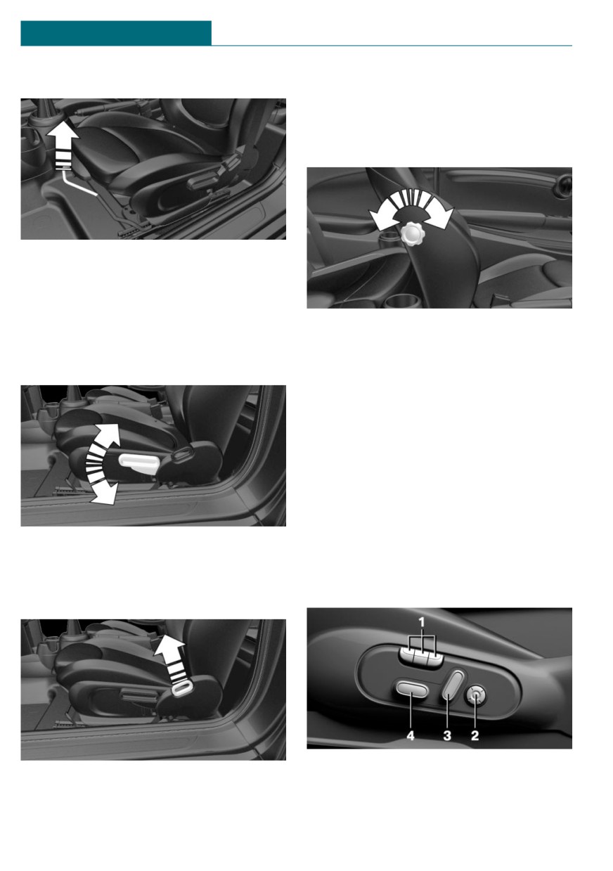
1
Forward/backward
Warning
2
Thigh support
Seat adjustments while driving can lead to
3
Height
unexpected movements of the seat. Vehi-
cle control could be lost. There is a risk of
4
Backrest tilt
accident. Only adjust the seat on the driv-
er's side when the vehicle is stationary.
81
CONTROLS
Seats, mirrors, and steering wheel
Forward/backward
Lumbar support
The curvature of the seat backrest can be
adjusted in a way that it supports the lum-
bar region of the spine. The lower back and
the spine are supported for upright posture.
Pull the lever and slide the seat in the de-
sired direction.
After releasing the lever, move the seat for-
ward or back slightly making sure it en-
gages properly.
Turn the wheel in order to increase or de-
crease the curvature.
Height
Electrically adjustable seats
General information
The seat setting for the driver's seat is
stored for the profile currently used. When
the vehicle is unlocked via the vehicle key,
the position is automatically retrieved if the
function, refer to page 74, is activated for
this purpose.
The current seat position can be stored us-
Pull the lever up or press it down as often as
ing the memory function, refer to page 88.
needed to reach the desired height.
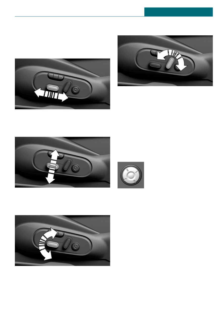
Overview
Backrest tilt
1
Memory function
Pull the lever, and apply your weight to the
2
Lumbar support
backrest or lift it off, as necessary.
82
Seats, mirrors, and steering wheel
CONTROLS
3
Backrest tilt
Backrest tilt
4
Forward/backward, height, seat tilt
Forward/backward
Move switch forward or backward.
Lumbar support
Push switch forward or backward.
Concept
The curvature of the seat backrest can be
Height
adjusted in a way that it supports the lum-
bar region of the spine. The lower back and
the spine are supported for upright posture.
Adjusting
- Press the front/rear sec-
tion of the button:
The curvature is in-
creased/decreased.
- Press the upper/lower sec-
Push switch up or down.
tion of the button:
The curvature is shifted
Seat tilt
up/down.
Move switch up or down.
83
CONTROLS
Seats, mirrors, and steering wheel
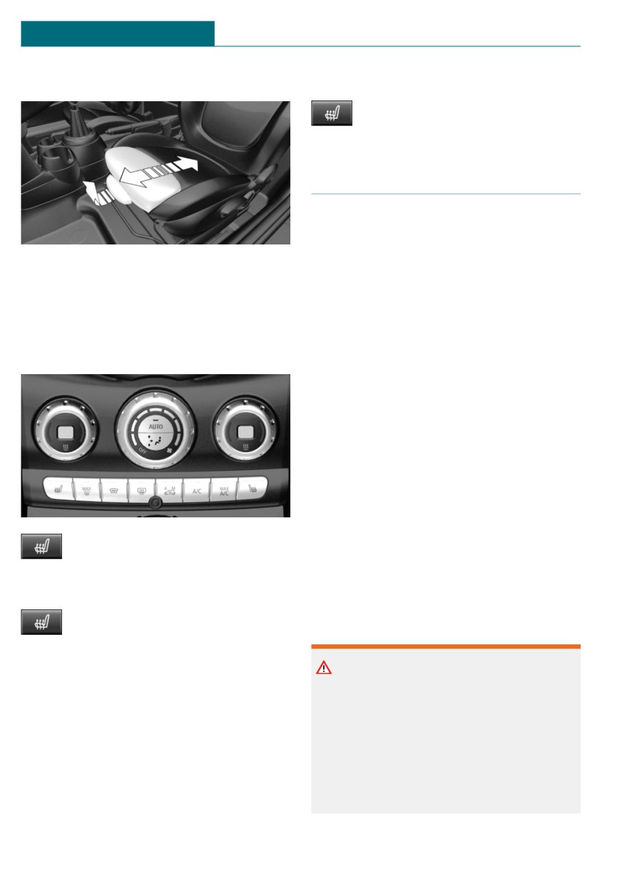
Thigh support
Switching off
Press and hold the button until the
LEDs go out.
Safety belts
Number of safety belts and safety
belt buckles
Pull the lever at the front of the seat and ad-
The vehicle is fitted with five safety belts to
just the thigh support.
ensure occupant safety. However, they can
only offer protection when adjusted cor-
rectly.
Front seat heating
The two outer safety belt buckles of the rear
seat are intended for the persons sitting on
Overview
the left and right.
The center safety belt buckle of the rear
seat is intended for the person sitting in the
middle.
General information
Always make sure that safety belts are be-
ing worn by all occupants before driving off.
Although airbags enhance safety by provid-
ing added protection, they are not a substi-
Seat heating
tute for safety belts.
The upper shoulder strap's anchorage point
will be correct for adult seat occupants of
Switching on
every build if the seat is correctly adjusted.
Press the button once for each tem-
perature level.
Safety information
The maximum temperature is reached when
three LEDs are lit.
Warning
If the trip is continued within approx.
Use of a safety belt to buckle more than
15 minutes after a stop, seat heating is acti-
one person will potentially defeat the abil-
vated automatically with the temperature
ity of the safety belt to serve its protective
selected last.
function. There is a risk of injuries or dan-
When GREEN Mode is activated, refer to
ger to life. Do not allow more than one per-
page 230, the heating output is reduced.
son to wear a single safety belt. Infants
and children are not allowed on an occu-
pant's lap, but must be transported and se-
84
Seats, mirrors, and steering wheel
CONTROLS
cured in designated child restraint sys-
Correct use of safety belts
tems.
- Wear the safety belt twist-free and tight
to your body over your lap and should-
ers.
Warning
- Wear the safety belt deep on your hips
The efficacy of safety gear, including
over your lap. The safety belt may not
safety belts, can be limited or lost when
press on your stomach.
safety belts are fastened incorrectly. An
- Do not rub the safety belt against sharp
incorrectly fastened safety belt can cause
edges, or guide it or jam it in across
additional injuries, for instance in the
hard or fragile objects.
event of an accident, braking or evasive
- Avoid thick clothing.
maneuvers. There is a risk of injuries or
danger to life. Make sure that all occu-
- Re-tighten the safety belt frequently up-
pants are wearing safety belts correctly.
ward around your upper body.
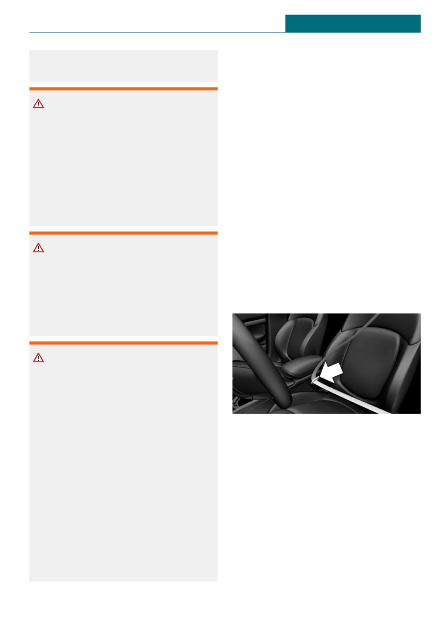
Buckling the safety belt
Warning
1. Guide the safety belt slowly over
With a rear backrest that is not locked, the
shoulder and hip to put it on.
protective function of the middle safety
2. Insert the tongue plate into the safety
belt is not guaranteed. There is a risk of
belt buckle. The safety belt buckle must
injuries or danger to life. If you are using
engage audibly.
the middle safety belt, lock the wider rear
seat backrest.
Warning
The efficacy of safety gear, including
safety belts, may not be fully functional or
fail in the following situations:
- The safety belts or safety belt buckles
are damaged, soiled, or changed in
any other way.
Unbuckling the safety belt
- Belt tensioners or belt retractors
1. Hold the safety belt firmly.
were modified.
2. Press the red button in the belt buckle.
Safety belts can be imperceptibly damaged
3. Guide the safety belt back into its roll-
in the event of an accident. There is a risk
up mechanism.
of injuries or danger to life. Do not modify
safety belts, safety belt buckles, belt ten-
sioners, belt retractors or belt anchors and
keep them clean. Have the safety belts
checked after an accident at the dealer’s
service center or another qualified service
center or repair shop.
85
CONTROLS
Seats, mirrors, and steering wheel
Safety belt reminder for driver's
Warning
seat and front passenger seat
Objects on the head restraint reduce the
Display in the instrument cluster
protective effect in the head and neck
area. There is a risk of injury.
The indicator light lights up and a
- Do not use seat or head restraint cov-
signal sounds. Make sure that the
ers.
safety belts are positioned correctly.
The safety belt reminder can also be acti-
- Do not hang objects, for instance
vated if objects are placed on the front pas-
clothes hangers, directly on the head
senger seat.
restraint.
- Only use accessories that have been
determined to be safe for attachment
to a head restraint.
Front head restraints
- Do not use any accessories, for in-
stance pillows, while driving.
Safety information
Adjusting the height: John Cooper
Warning
Works sport seat
A missing protective effect due to re-
The height of the head restraints cannot be
moved or not correctly adjusted head re-
set.
straints can cause injuries in the head and
neck area. There is a risk of injury.
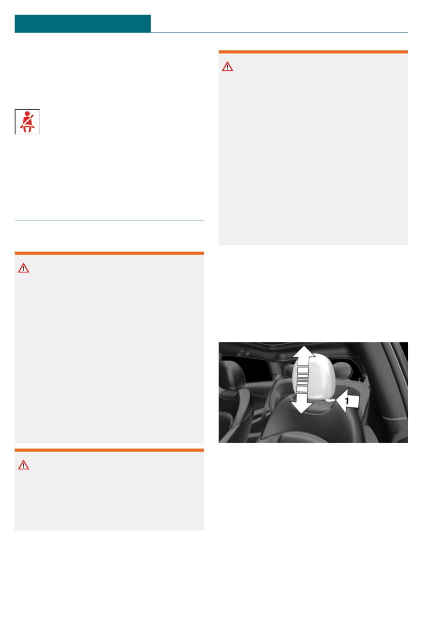
Adjusting the height
- Before driving, install the removed
head restraints on the occupied seats.
- Adjust the head restraint so its center
supports the back of the head at as
close to eye level as possible.
- Adjust the distance so that the head
restraint is as close as possible to the
back of the head. Adjust the distance
via the backrest tilt as needed.
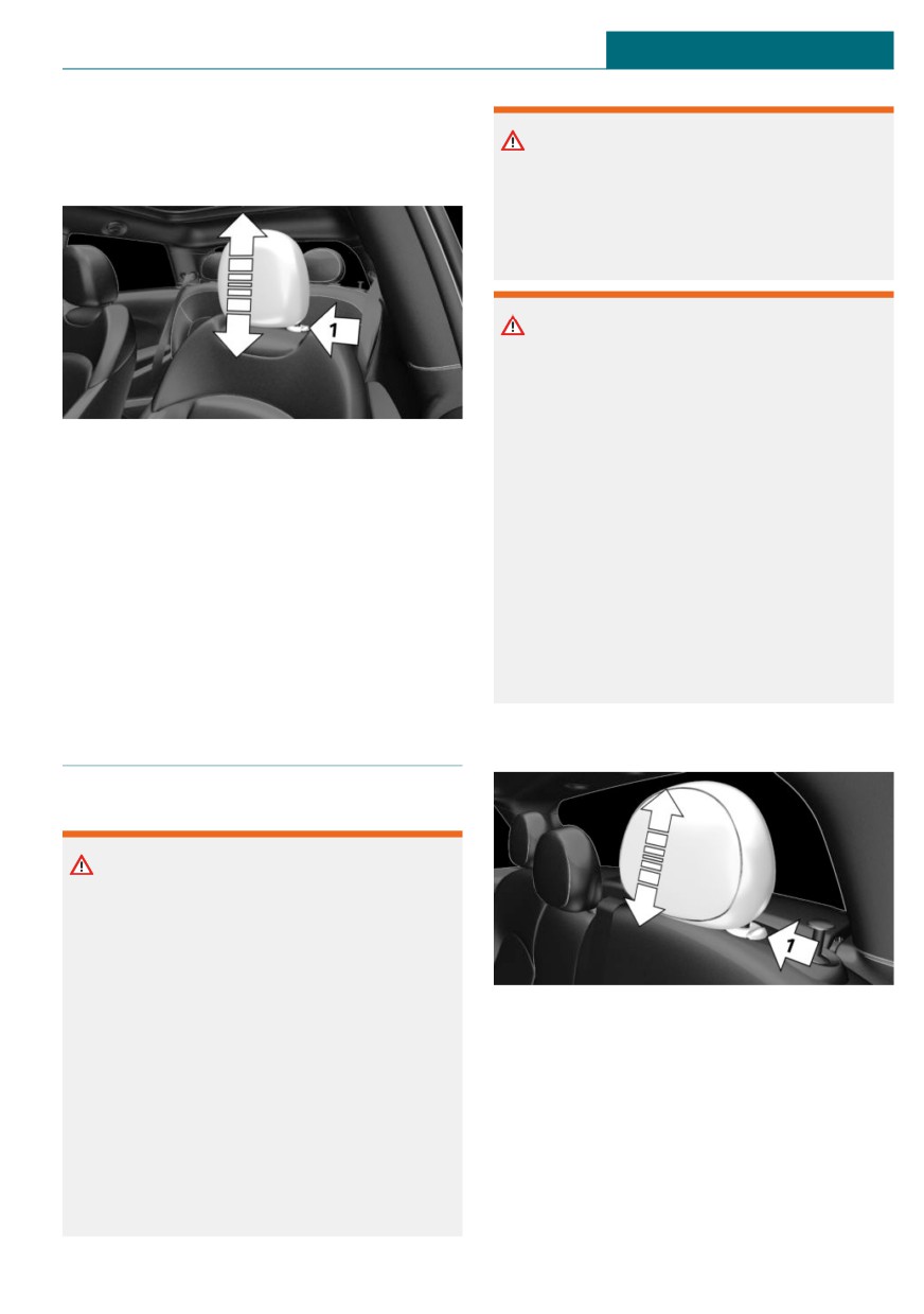
- To lower: press the button, arrow 1, and
Warning
push the head restraint down.
Body parts can be jammed when moving
- To raise: push the head restraint up.
the head restraint. There is a risk of injury.
After setting the height, make sure that the
Make sure that the area of movement is
head restraint engages correctly.
clear when moving the head restraint.
Removing: John Cooper Works
sport seat
The head restraints cannot be removed.
86
Seats, mirrors, and steering wheel
CONTROLS
Removing
Warning
Only remove the head restraint if no one
will be sitting in the seat in question.
Body parts can be jammed when moving
the head restraint. There is a risk of injury.
Make sure that the area of movement is
clear when moving the head restraint.
Warning
Objects on the head restraint reduce the
protective effect in the head and neck
area. There is a risk of injury.
- Do not use seat or head restraint cov-
1. If necessary, fold the rear seat backrest
ers.
forward.
- Do not hang objects, for instance
2. Pull head restraint up as far as possible.
clothes hangers, directly on the head
3. Press the button, arrow 1, and pull the
restraint.
head restraint out completely.
- Only use accessories that have been
determined to be safe for attachment
Installing
to a head restraint.
Proceed in the reverse order to install the
- Do not use any accessories, for in-
head restraint.
stance pillows, while driving.
Rear head restraints
Adjusting the height
Safety information
Warning
A missing protective effect due to re-
moved or not correctly adjusted head re-
straints can cause injuries in the head and
neck area. There is a risk of injury.
- Before driving, install the removed
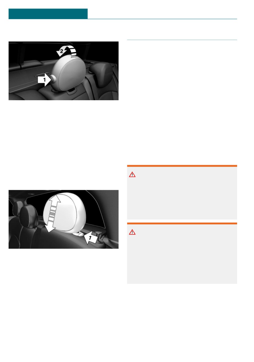
- To lower: press the button, arrow 1, and
head restraints on the occupied seats.
push the head restraint down.
- Adjust the head restraint so its center
- To raise: push the head restraint up.
supports the back of the head at as
After setting the height, make sure that the
close to eye level as possible.
head restraint engages correctly.
- Adjust the distance so that the head
restraint is as close as possible to the
back of the head. Adjust the distance
via the backrest tilt as needed.
87
CONTROLS
Seats, mirrors, and steering wheel
Fold down
Memory function
Concept
The following settings can be stored and, if
necessary, retrieved using the memory
function:
- Seat position.
- Exterior mirror position.
- Height of the Head-up Display.
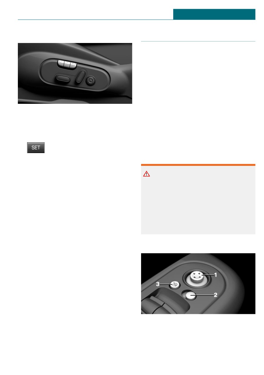
- To fold down: press the button, arrow 1,
and press down the head restraint, ar-
General information
row 2.
Different settings can be assigned to two
- Forward: fold the head restraint toward
memory locations.
the front as far as it will go. Make sure
The adjustment of the lumbar support is not
that the head restraint engages cor-
stored.
rectly.
Safety information
Removing
Only remove the head restraint if no one
Warning
will be sitting in the seat in question.
There is a risk of jamming when moving
the seats. There is a risk of injury or risk
of damage to property. Make sure that the
area of movement of the seat is clear prior
to any adjustment.
Warning
Using the memory function while driving
can lead to unexpected movements of the
1. Fold down the rear seat backrest, refer
seat. Vehicle control could be lost. There is
to page 221, in question.
a risk of accident. Only retrieve the mem-
ory function when the vehicle is station-
2. Pull head restraint up against the resist-
ary.
ance.
3. Press the button, arrow 1, and pull the
head restraint out completely.
Installing
Proceed in the reverse order to install the
head restraint.
88
Seats, mirrors, and steering wheel
CONTROLS
Overview
Mirrors
Exterior mirrors
General information
The mirror on the front passenger side is
more curved than the driver's side mirror.
The mirror setting is stored for the driver
profile currently in use. When the vehicle is
unlocked via the vehicle key, the position is
automatically retrieved if the function, refer
Storing
to page 74, is activated for this purpose.
1. Switch on the ignition.
The current exterior mirror position can be
2. Set the desired position.
stored using the memory function, refer to
page 88.
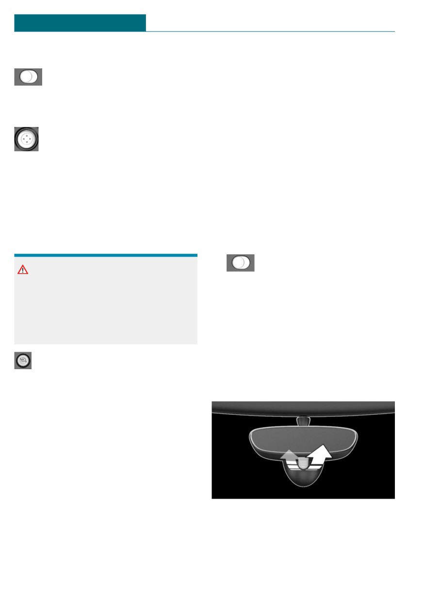
3.
Press the button. The LED in the
button lights up.
Safety information
4. Press the desired button 1 or 2 while the
LED is lit. The LED goes out.
Warning
Objects reflected in the mirror are closer
Calling up settings
than they appear. The distance to the traf-
The stored position is called up automati-
fic behind could be incorrectly estimated,
cally.
for instance while changing lanes. There is
Press the desired button 1 or 2.
a risk of accident. Estimate the distance to
the traffic behind by looking over your
The procedure stops when a seat adjust-
shoulder.
ment switch or one of the memory buttons
is pressed.
Once underway, adjustment of the seat po-
Overview
sition on the driver's side is disabled after a
short while.
Call up deactivated
After a brief period, calling up stored seat
positions is deactivated to save battery
power.
To reactivate calling up of a seat position:
- Open or close the door or split doors.
- Press a button on the vehicle key.
1
Adjusting
– Press the Start/Stop button.
2
Selecting a mirror, Automatic Curb Mon-
itor
3
Folding in and out
89
CONTROLS
Seats, mirrors, and steering wheel
Selecting a mirror
Automatic dimming feature
To change over to the other mirror:
The exterior mirror on the driver's side is
automatically dimmed. Photocells in the
Slide the switch.
car's interior mirror, refer to page 91, are
used to control this.
Adjusting electrically
Automatic Curb Monitor, exterior
Press the button.
mirror
The mirror movement follows the
button movement.
Concept
If reverse gear is engaged, the mirror glass
Malfunction
on the front passenger side is tilted down-
In case of an electrical malfunction, adjust
ward. This improves your view of the curb
the mirror by pressing the edges of the mir-
and other formatting issue - low-lying ob-
ror glass.
stacles when parking, for instance.
Folding in and out
Activating
1.
slide the switch to the driver's
NOTICE
side mirror position.
Depending on the vehicle width, the vehi-
2. Engage selector lever position R.
cle can be damaged in vehicle washes.
There is a risk of damage to property. Be-
Deactivating
fore washing, fold in the mirrors by hand
or with the button.
Slide the switch to the passenger's side mir-
ror position.
Press the button.
Interior mirror, manually dimmable
Folding is only possible up to a speed of ap-
Flip lever
prox. 15 mph/20 km/h.
Folding the mirrors in and out is helpful in
the following situations:
- In vehicle washes.
- On narrow roads.
Mirrors that were folded in are folded out
automatically at a speed of approx.
25 mph/40 km/h.
Automatic heating
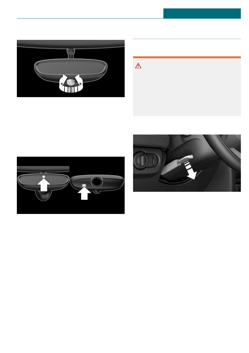
To reduce the blinding effect of the interior
Both exterior mirrors are automatically
mirror, flip the lever forward.
heated as needed and when the ignition is
switched on.
90
Seats, mirrors, and steering wheel
CONTROLS
Turn knob
Steering wheel
Safety information
Warning
Steering wheel adjustments while driving
can lead to unexpected steering wheel
movements. Vehicle control could be lost.
There is a risk of accident. Adjustng the
steering wheel while the vehicle is sta-
Turn the knob to reduce the blinding effect
tionary only.
by the interior mirror.
Interior mirror, automatic dimming
Adjusting
feature
Overview
1. Fold the lever down.
2. Move the steering wheel to the prefer-
red height and angle to suit your seating
Photocells are used for control:
position.
- In the mirror glass.
3. Fold the lever back up.
- On the back of the mirror.
Functional requirements
- Keep the photocells clean.
- Do not cover the area between the inte-
rior mirror and the windshield.
91

CONTROLS
Transporting children safely
Transporting children safely
Vehicle features and options
Warning
A heated vehicle may result in death to
This chapter describes all standard, country-
persons, especially children, or animals.
specific and optional features offered with
There is a risk of injuries or danger to life.
the series. It also describes features and
Do not leave persons, especially children,
functions that are not necessarily available
or animals unattended in the vehicle.
in your vehicle, e.g., due to the selected op-
tions or country versions. This also applies
to safety-related functions and systems.
When using these functions and systems,
Warning
the applicable laws and regulations must be
Exposure to intense sunlight can cause
observed.
child restraint systems and their compo-
nents to become very hot. Persons may
sustain burn injuries when touching the
The right place for children
hot components. There is a risk of injury.
Do not expose the child restraint system to
direct sunlight or cover where necessary.
Safety information
If necessary, let the child restraint system
cool down before transporting a child. Do
Warning
not leave children unattended in the vehi-
Unattended children or animals in the ve-
cle.
hicle can cause the vehicle to move and
endanger themselves and traffic, for in-
Always transport children in the
stance due to the following actions:
rear seat
- Pressing the Start/Stop button.
- Releasing the parking brake.
General information
- Opening and closing the doors or
Accident research shows that the safest
windows.
place for children is in the rear seat.
- Engaging selector lever position N.
Transport children younger than 13 years of
- Using vehicle equipment.
age or shorter than 5 ft/150 cm only in the
There is a risk of accidents or injuries. Do
rear seat in suitable child restraint systems
not leave children or animals unattended
designed for the age, weight and size of the
in the vehicle. Take the vehicle key with
child. Children 13 years of age or older must
you when exiting and lock the vehicle.
wear a safety belt as soon as a suitable child
restraint system can no longer be used due
to their age, weight, or size.
92

Transporting children safely
CONTROLS
Safety information
Warning
The stability of the child restraint system
Warning
is limited or compromised with incorrect
The safety belt cannot be fastened cor-
seat adjustment or improper installation of
rectly on children shorter than 5 ft,
the child seat. There is a risk of injuries or
150 cm without suitable additional child
danger to life. Make sure that the child re-
restraint systems. The efficacy of safety
straint system fits securely against the
gear, including safety belts, can be limited
backrest. If possible, adjust the backrest
or lost when safety belts are fastened in-
tilt for all affected backrests and correctly
correctly. An incorrectly fastened safety
adjust the seats. Make sure that seats and
belt can cause additional injuries, for in-
backrests are securely engaged or locked.
stance in the event of an accident, braking
If possible, adjust the height of the head
or evasive maneuvers. There is a risk of in-
restraints or remove them.
juries or danger to life. Secure children
shorter than 5 ft, 150 cm using suitable
child restraint systems.
Installing child restraint sys-
Children on the front passenger
tems
seat
General information
General information
Pay attention to the specifications of the
Before using a child restraint system on the
child restraint system manufacturer when
front passenger seat, ensure that the front,
selecting, installing, and using child re-
knee, and side airbags on the front passen-
straint systems.
ger side are deactivated. For automatic de-
activation of front-seat passenger airbags,
Safety information
refer to page 150.
Warning
Safety information
The protective effect of child restraint sys-
tems and their fastening systems which
Warning
have been damaged or exposed to an acci-
Active front-seat passenger airbags can in-
dent can be limited or lost. A child cannot
jure a child in a child restraint system
be properly restrained in the event of an
when the airbags are activated. There is a
accident, braking or evasive maneuvers.
risk of injury. Make sure that the front-
There is a risk of injuries or danger to life.
seat passenger airbags are deactivated and
Do not use child restraint systems which
that the PASSENGER AIRBAG OFF indica-
have been damaged or exposed to an acci-
tor light lights up.
dent.
If a child restraint system and its fasten-
ing system has been damaged or exposed
to an accident, have these systems
checked and replaced by the dealer's serv-
93
CONTROLS
Transporting children safely
ice center or another qualified service cen-
and to offer optimal protection in the event
ter or repair shop.
of an accident.
If the upper anchorage of the safety belt is
located in front of the belt guide of the child
Warning
seat, move the front passenger seat care-
fully forward until the best possible belt
The stability of the child restraint system
guide position is reached.
is limited or compromised with incorrect
seat adjustment or improper installation of
the child seat. There is a risk of injuries or
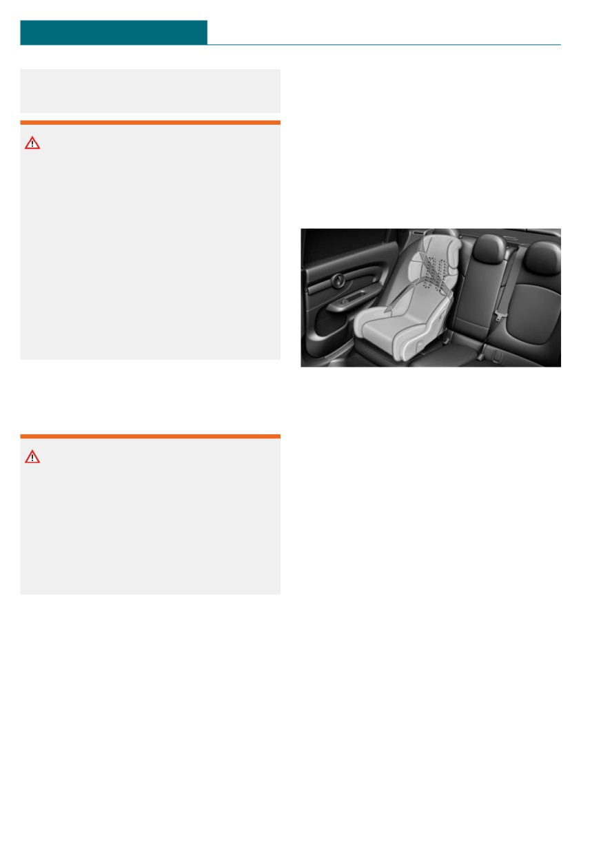
Child seat security
danger to life. Make sure that the child re-
straint system fits securely against the
backrest. If possible, adjust the backrest
tilt for all affected backrests and correctly
adjust the seats. Make sure that seats and
backrests are securely engaged or locked.
If possible, adjust the height of the head
restraints or remove them.
On the front passenger seat
The rear safety belts and the front passen-
ger safety belt can be permanently locked to
Deactivating airbags
fasten child restraint systems.
Locking the safety belt
Warning
Active front-seat passenger airbags can in-
1. Pull out the belt strap completely.
jure a child in a child restraint system
2. Secure the child restraint system with
when the airbags are activated. There is a
the safety belt.
risk of injury. Make sure that the front-
3. Allow the belt strap to be pulled in and
seat passenger airbags are deactivated and
pull it tight against the child restraint
that the PASSENGER AIRBAG OFF indica-
system. The safety belt is locked.
tor light lights up.
Unlocking the safety belt
Before installing a child restraint system in
the front passenger seat, make sure that the
1. Unbuckle the safety belt buckle.
front, knee and side airbags on the front
2. Remove the child restraint system.
passenger side are deactivated.
3. Allow the belt strap to be pulled in com-
Deactivate the front-seat passenger airbags
pletely.
automatically, refer to page 150.
Seat position and height
Before installing a child restraint system,
move the front passenger seat as far back as
possible and adjust its height to the highest
and thus best possible position for the belt
94
Transporting children safely
CONTROLS
LATCH child restraint fixing
Position
system
Symbol
Meaning
The corresponding symbol
General information
shows the mounts for the
LATCH: Lower Anchors and Tether for Chil-
lower LATCH anchors.
dren.
Seats equipped with lower
Pay attention to the operating and safety in-
anchors are marked with a
formation from the child restraint system
pair, (2), of LATCH symbols.
manufacturer when installing and using
For vehicles equipped with
LATCH child restraint fixing systems.
a middle seat:
It is not recommended to
Mounts for the lower LATCH
use the inner lower anchors
anchors
of standard outer LATCH
The lower anchors may be used to attach
positions to fasten a child
the CRS to the vehicle seat up to a com-
restraint system on the
bined child and CRS weight of 65 lbs/30 kg
middle seat. Use the vehicle
when the child is restrained by the internal
safety belt instead for the
harnesses.
middle seat.
Safety information
Before installing LATCH child
restraint fixing systems
Warning
Pull the safety belt away from the area of
If the LATCH child restraint fixing sys-
the child restraint system.
tems are not correctly engaged, the protec-
tive effect of the LATCH child restraint
Assembly of LATCH child restraint
fixing system can be limited. There is a
fixing systems
risk of injuries or danger to life. Make sure
that the lower anchors are securely en-
1. Install child restraint system, see manu-
gaged and that the LATCH child restraint
facturer's information.
fixing system fits securely against the
2. Ensure that both LATCH anchors are
backrest.
properly engaged.
95
CONTROLS
Transporting children safely
Child restraint systems with tether
Routing the retaining strap
strap
Safety information
Warning
If the upper retaining strap is incorrectly
used for the child restraint system, the
protective effect can be reduced. There is
a risk of injury. Make sure that the upper
retaining strap does not run over sharp
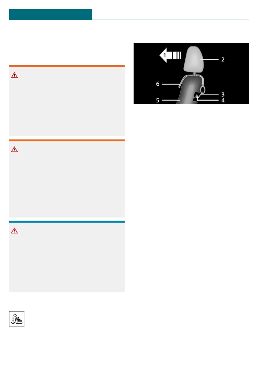
1
Direction of travel
edges and is not twisted as it passes the
2
Head restraint
upper anchor.
3
Hook for upper retaining strap
4
Anchor
5
Seat backrest
Warning
6
Upper retaining strap
If the rear backrest is not locked, the pro-
tective effect of the child restraint system
is limited or there is none. In certain situa-
Attaching the upper retaining strap to
tions, for instance braking maneuvers or
the anchor
in case of an accident, the rear backrest
1. Raise the head restraint, if needed.
can fold forward. There is a risk of injuries
or danger to life. Make sure that the rear
2. On the rear seat: Guide the upper retain-
backrests are locked.
ing strap between or along both sides of
the supports of the head restraint to the
anchor.
NOTICE
3. Attach the hook of the retaining strap to
the anchor on the rear seat.
The anchors for the upper retaining straps
of child restraint systems are only pro-
4. Tighten the retaining strap by pulling it
vided for these retaining straps. When
down.
other objects are mounted, the anchors
can be damaged. There is a risk of damage
to property. Only mount child restraint
systems to the upper anchors.
Anchors
The respective symbol shows the an-
chor for the upper retaining strap.
Seats with an upper top tether are
marked with this symbol. It can be found on
the rear seat backrest or the rear window
shelf.
96
Transporting children safely
CONTROLS
Locking the doors and win-
dows
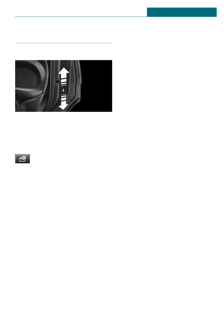
Doors
Push the locking lever on the rear doors up.
The door can now be opened from the out-
side only.
Safety switch for the rear
Press the button on the driver's
door if children are being trans-
ported in the rear.
This locks various functions so that they
cannot be operated from the rear: safety
switch, refer to page 78.
97
CONTROLS
Driving
Driving
To save battery power when the engine is
Vehicle features and options
off, switch off the ignition and any unneces-
sary electronic systems/power consumers.
This chapter describes all standard, country-
specific and optional features offered with
Ignition off
the series. It also describes features and
functions that are not necessarily available
Manual transmission: press the Start/Stop
in your vehicle, e.g., due to the selected op-
button again without stepping on the clutch
tions or country versions. This also applies
pedal.
to safety-related functions and systems.
Steptronic transmission: shift to selector
When using these functions and systems,
lever position P, press the Start/Stop button
the applicable laws and regulations must be
again without stepping on the brake.
observed.
All indicator lights in the instrument cluster
go out.
To save battery power when the engine is
Start/Stop button
off, switch off the ignition and any unneces-
sary electronic systems/power consumers.
Concept
Safety measures
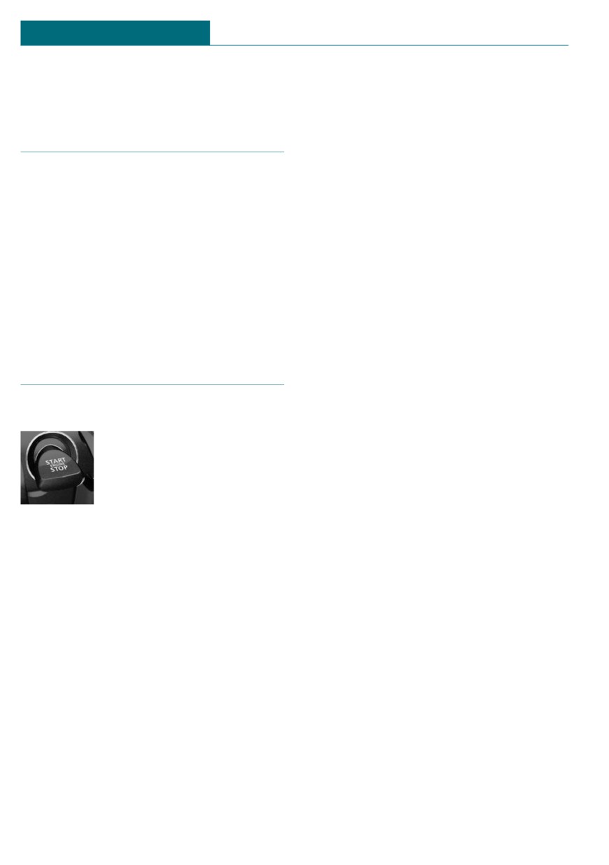
Pressing the Start/Stop button
switches the ignition on or off
The ignition is switched off automatically in
and starts the engine.
the following situations while the vehicle is
stationary and the engine is off:
Steptronic transmission: the
engine starts in selector lever
-
When locking the vehicle, even if the
position P or N with the brake pedal pressed
low beams are switched on.
when you press the Start/Stop button.
-
Shortly before the battery is discharged
Manual transmission: the engine starts with
completely, so that the engine can still
the clutch pedal pressed when the Start/
be started. This function is only availa-
Stop button is pressed.
ble when the low beams are switched
off.
-
When opening or closing the driver
Ignition on
door, if the driver's safety belt is un-
Manual transmission: press the Start/Stop
buckled and the low beams are switched
button without stepping on the clutch
off.
pedal.
-
While the driver's safety belt is unbuck-
Steptronic transmission: press the Start/
led with driver's door open and low
Stop button, but do not press on the brake
beams off.
pedal at the same time.
-
When the front doors are opened if
All vehicle systems are ready for operation.
there is no other person sitting in the
Most of the indicator/warning lights in the
front seats.
instrument cluster light up for a varied
length of time.
98
Driving
CONTROLS
– The low beams switch to parking lights
– Shortly before the battery is discharged
after some minutes of no use.
completely, so that the engine can still
be started.
Steptronic transmission with a tap-operated
selector lever, refer to page 115: when
switching off the ignition, the selector lever
position P is engaged automatically if the
Starting the engine
selector lever position R, D or M/S is en-
gaged.
Safety information
Radio-ready state
DANGER
General information
If the exhaust pipe is blocked or ventila-
tion is insufficient, harmful exhaust gases
In the radio-ready state, certain power con-
can enter into the vehicle. The exhaust
sumers remain ready for operation.
gases contain pollutants which are color-
less and odorless. In enclosed areas, ex-
Activating
haust gases can also accumulate outside of
With the engine running, press the Start/
the vehicle. There is danger to life. Keep
Stop button.
the exhaust pipe free and ensure sufficient
If the engine is not running and the ignition
ventilation.
is switched on: the system automatically ac-
tivates radio-ready state when the door is
opened if the lights are switched off or the
Warning
daytime running lights are switched on.
An unsecured vehicle can begin to move
Radio-ready state remains active if, for in-
and possibly roll away. There is a risk of
stance the ignition is automatically
accident. Before exiting, secure the vehi-
switched off for the following reasons:
cle against rolling.
- Opening or closing the driver's door.
In order to ensure that the vehicle is se-
- Unfastening of the driver's safety belt.
cured against rolling away, follow the fol-
- When automatically switching from low
lowing:
beams to parking lights.
- Set the parking brake.
- On uphill grades or on a downhill
Switching off automatically
slope, turn the front wheels in the di-
The radio-ready state is switched off auto-
rection of the curb.
matically in the following situations:
- On uphill grades or on a downhill
- If the driver's or front passenger door is
slope, also secure the vehicle, for in-
opened when exiting the vehicle, with
stance with a wheel chock.
the engine switched off manually.
- If the ignition is switched off manually
with the Start/Stop button.
NOTICE
- After approx. 8 minutes.
In the case of repeated starting attempts
or repeated starting in quick succession,
- When the vehicle is locked using the
the fuel is not burned or is inadequately
central locking system.
burned. The catalytic converter can over-
99
CONTROLS
Driving
heat. There is a risk of damage to property.
Engine stop
Avoid repeated starting in quick succes-
sion.
Safety information
Gasoline engine
Warning
Depending on the motorization, the full
Unattended children or animals in the ve-
drive power may not be available for ap-
hicle can cause the vehicle to move and
proximately 30 seconds after starting the
endanger themselves and traffic, for in-
engine. In this case, the vehicle will not ac-
stance due to the following actions:
celerate as usual.
- Pressing the Start/Stop button.
- Releasing the parking brake.
Steptronic transmission
- Opening and closing the doors or
Starting the engine
windows.
1. Depress the brake pedal.
- Engaging selector lever position N.
- Using vehicle equipment.
2. Engage selector lever position P or N.
There is a risk of accidents or injuries. Do
3. Press the Start/Stop button.
not leave children or animals unattended
The ignition is activated automatically for a
in the vehicle. Take the vehicle key with
brief time and is stopped as soon as the en-
you when exiting and lock the vehicle.
gine starts.
Manual transmission
Warning
An unsecured vehicle can begin to move
Starting the engine
and possibly roll away. There is a risk of
1. Depress the brake pedal.
accident. Before exiting, secure the vehi-
2. Press on the clutch pedal and shift to
cle against rolling.
neutral.
In order to ensure that the vehicle is se-
3. Press the Start/Stop button.
cured against rolling away, follow the fol-
lowing:
The ignition is activated automatically for a
brief time and is stopped as soon as the en-
- Set the parking brake.
gine starts.
- On uphill grades or on a downhill
slope, turn the front wheels in the di-
rection of the curb.
- On uphill grades or on a downhill
slope, also secure the vehicle, for in-
stance with a wheel chock.
100
Driving
CONTROLS
Steptronic transmission
Engine stop
Switching off the engine
Functional requirements
1. When the vehicle is stationary, apply
The engine is switched off automatically
the parking brake.
during a stop under the following condi-
tions:
2. Engage selector lever position P.
Manual transmission:
3. Press the Start/Stop button.
- Neutral is engaged and the clutch pedal
The engine is switched off.
is not pressed.
The radio-ready state is switched on.
- The driver's safety belt is buckled or the
driver's door is closed.
Manual transmission
Steptronic transmission:
Switching off the engine
- The selector lever is in selector lever po-
sition D.
1. With the vehicle at a standstill, press
- The brake pedal remains depressed
the Start/Stop button.
while the vehicle is stopped.
The engine is switched off.
- The driver's safety belt is buckled or the
The radio-ready state is switched on.
driver's door is closed.
2. Shift into first gear or reverse.
In order to be able to release the brake
3. Set the parking brake.
pedal, engage the selector lever in position
P. The engine remains off.
To continue driving depress the brake
Auto Start/Stop function
pedal. When a gear is engaged, the engine
starts automatically.
Concept
The air flow from the air conditioner is re-
duced when the engine is switched off.
The Auto Start/Stop function helps save
fuel. The system switches off the engine
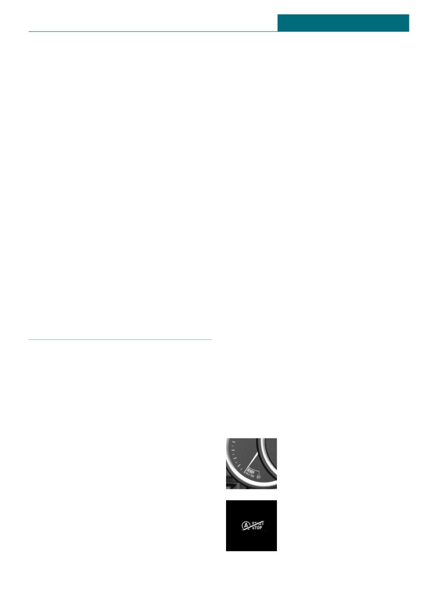
Displays in the instrument cluster
during a stop, for instance in traffic conges-
tion or at traffic lights. The ignition remains
Instrument cluster without enhanced
switched on. The engine starts automati-
features: display
cally for driving off.
After each engine start using the Start/Stop
The display indicates that the
button, the Auto Start/Stop function is
Auto Start/Stop function is
ready and is activated at speeds faster than
ready for an Automatic engine
about 3 mph/5 km/h.
start.
Depending on the selected driving mode, re-
fer to page 171, the system is automatically
The display indicates that the
activated or deactivated.
conditions for an automatic
engine stop have not been
met.
101
CONTROLS
Driving
Functional limitations
Some indicator lights light up for a varied
length of time.
The engine is not switched off automatically
in the following situations:
The engine can only be started via the
Start/Stop button.
-
External temperature too low.
–
The external temperature is high and au-
Functional limitations
tomatic climate control is running.
Even if driving off was not intended, the de-
-
The car's interior has not yet been
activated engine starts up automatically in
heated or cooled to the required level.
the following situations:
-
The engine is not yet at operating tem-
-
Excessive warming of the car's interior
perature.
when the air conditioning is switched
-
The wheels are at a sharp angle or the
on.
steering wheel is being turned.
-
When the steering wheel is turned.
-
After driving in reverse.
–
Steptronic transmission: change from
–
Fogging of the windows when the auto-
selector lever position D to R, N or M/S.
matic climate control is switched on.
-
Steptronic transmission: change from
-
The vehicle battery charge is very low.
selector lever position P to R, N, D or
–
At higher elevations.
M/S.
–
The hood is unlocked.
-
The vehicle begins rolling.
–
The parking assistant is activated.
–
Fogging of the windows when the auto-
matic climate control is switched on.
–
Stop-and-go traffic.
-
The vehicle battery charge is very low.
–
Selector lever in selector lever position
R, N or M/S.
–
Excessive cooling of the car's interior
when the heating is switched on.
Starting the engine
–
Manual transmission: low brake vacuum
pressure; this can occur, for instance if
The engine starts automatically under the
the brake pedal is depressed a number
following conditions:
of times in succession.
- Manual transmission: clutch pedal is
pressed.
Additional Auto Start/Stop
- Steptronic transmission: by releasing
function
the brake pedal.
Depending on the vehicle equipment and
After the engine starts, accelerate as usual.
country-specific version, the vehicle fea-
tures a variety of sensors for assessing the
Safety mode
traffic situation. The Auto Start/Stop func-
After the engine switches off automatically,
tion uses this information to adapt to vari-
it will not start again automatically if any
ous traffic situations in a proactive manner.
one of the following conditions are met:
For instance, this applies to the following
- The driver's safety belt is unbuckled and
situations:
the driver's door is open.
- When a situation is detected in which
- The hood was unlocked.
the stopping time is expected to be very
short, the engine is not switched off au-
102
Driving
CONTROLS
tomatically. A message appears on the
2. Press the Start/Stop button. The ignition
Control Display, depending on the situa-
is switched off. The Auto Start/Stop
tion.
function is deactivated.
- When a situation is detected in which
3. Set the parking brake.
the vehicle needs to drive off immedi-
Manual transmission:
ately, the engine is started automati-
cally.
1. Press the Start/Stop button. The ignition
is switched off. The Auto Start/Stop
The function may be restricted if the navi-
function is deactivated.
gation data is invalid, outdated or not avail-
able, for example.
2. Shift into first gear or reverse.
3. Set the parking brake.
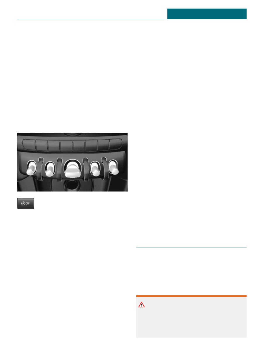
Switching the system on/off
Engine start as usual via Start/Stop button.
Using the button
Automatic deactivation
In certain situations, the Auto Start/Stop
function is deactivated automatically for
safety reasons, for instance if no driver is
detected.
Malfunction
The Auto Start/Stop function no longer
switches off the engine automatically. A
Check Control message is displayed. It is
Press the button.
possible to continue driving. Have the sys-
tem checked by a dealer's service center or
another qualified service center or repair
-
LED comes on: auto Start/Stop function
shop.
is deactivated.
The engine is started during an auto-
matic engine stop.
Parking brake
The engine can only be stopped or
started via the Start/Stop button.
Concept
-
LED goes out: auto Start/Stop function
is activated.
The parking brake is used to prevent the ve-
hicle from rolling when it is parked.
Switching off the vehicle during an
automatic engine stop
Safety information
During an automatic engine stop, the vehi-
cle can be switched off permanently, for in-
Warning
stance when leaving it.
An unsecured vehicle can begin to move
Steptronic transmission:
and possibly roll away. There is a risk of
accident. Before exiting, secure the vehi-
1. Engage selector lever position P.
cle against rolling.
103
CONTROLS
Driving
In order to ensure that the vehicle is se-
Setting
cured against rolling away, follow the fol-
lowing:
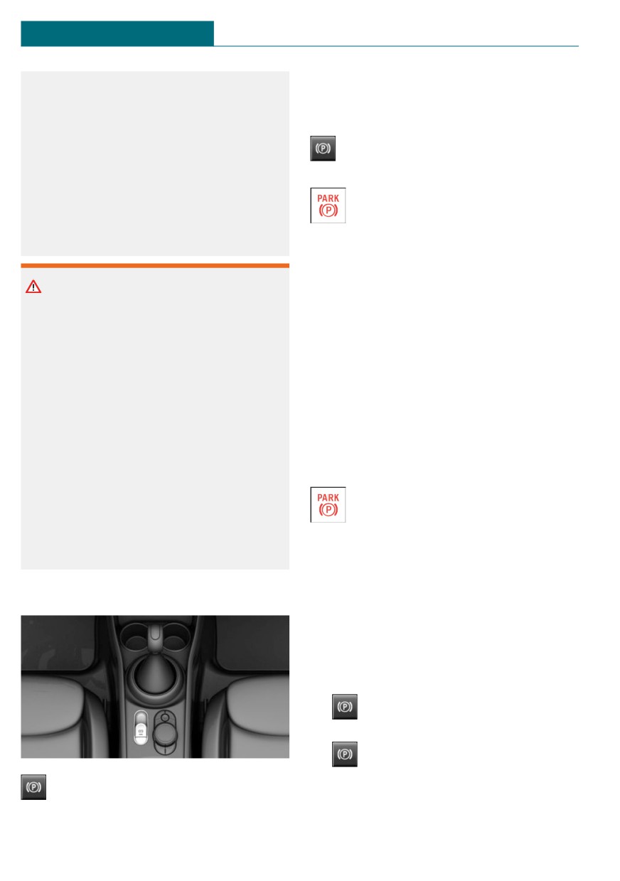
With a stationary vehicle
- Set the parking brake.
Pull the switch.
- On uphill grades or on a downhill
The LED lights up.
slope, turn the front wheels in the di-
rection of the curb.
The indicator light lights up red. The
- On uphill grades or on a downhill
parking brake is set.
slope, also secure the vehicle, for in-
stance with a wheel chock.
Depending on the stopping situation, the
parking brake is engaged automatically.
Steptronic transmission: in some parking
Warning
situations, the parking brake is automati-
Unattended children or animals in the ve-
cally engaged, when selector lever posi-
hicle can cause the vehicle to move and
tion P is engaged. In these cases, the park-
endanger themselves and traffic, for in-
ing brake is released automatically when
stance due to the following actions:
you leave the selector lever position P.
- Pressing the Start/Stop button.
While driving
- Releasing the parking brake.
To use as emergency brake while driving:
- Opening and closing the doors or
windows.
Pull the switch and hold it. The vehicle
brakes hard while the switch is being
- Engaging selector lever position N.
pulled.
- Using vehicle equipment.
The indicator light lights up red, a
There is a risk of accidents or injuries. Do
signal sounds and the brake lights
not leave children or animals unattended
light up.
in the vehicle. Take the vehicle key with
A Check Control message is displayed.
you when exiting and lock the vehicle.
If the vehicle is decelerated to a complete
stop, the parking brake is engaged.
Overview
Releasing
Releasing manually
1. Switch on the ignition.
2.
Manual transmission: press the
switch while the brake pedal is pressed.
Steptronic transmission: press the
switch while the brake is pressed or se-
Parking brake
lector lever position P is set.
The LED and indicator light go out.
104
Driving
CONTROLS
The parking brake is released.
2.
Press the switch while stepping on
the brake pedal or selector lever posi-
Automatic release in cars with
tion P is set.
Steptronic transmission
It may take several seconds for the brake to
For automatic release, step on the accelera-
be reactivated. Some mechanical sounds as-
tor pedal.
sociated with this process are normal.
The LED and indicator light go out.
The indicator light in the instrument
The parking brake is automatically released
cluster goes out as soon as the park-
when you step on the accelerator under the
ing brake is ready for operation.
following conditions:
- Engine on.
- Drive mode engaged.
Turn signal, high beams, head-
- Driver buckled in and doors closed.
light flasher
Automatic release in cars with manual
transmission
Turn signal
Drive off as usual. The parking brake disen-
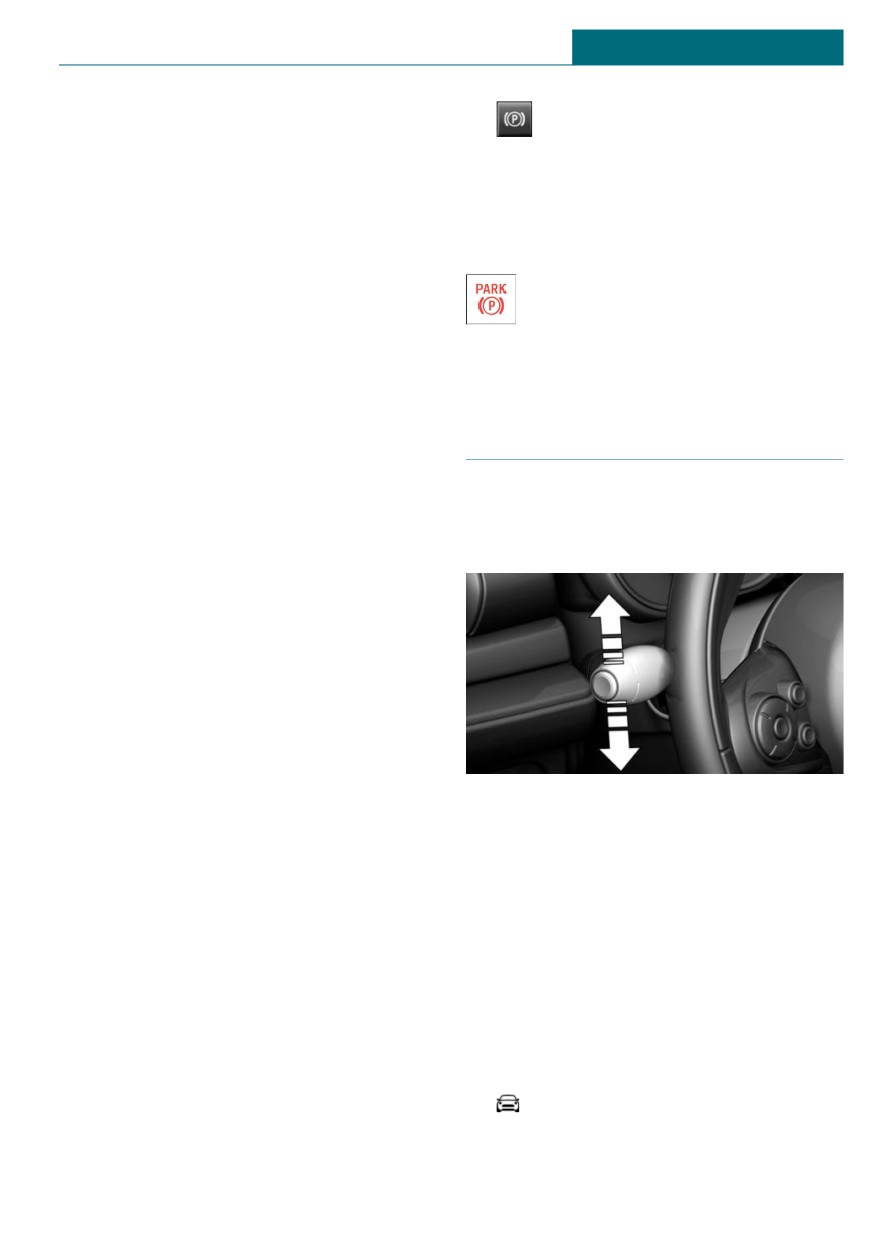
Using turn signals
gages when the clutch pedal is released.
The LED and indicator light go out.
Under the following conditions, the parking
brake is automatically released:
- Engine on.
- Gear engaged.
- Driver buckled in and doors closed.
- Engine power is sufficient to drive off.
Malfunction
Press the lever past the resistance point.
If the parking brake fails or malfunctions,
Canada: the lever returns into its starting
secure the vehicle against rolling before ex-
position after actuation. To switch off man-
iting.
ually, slightly tap the lever to the resistance
point.
A Check Control message is displayed.
Secure the vehicle against rolling away, for
instance with a wheel chock, after exiting
Triple turn signal activation
the vehicle.
Lightly tap the lever up or down.
The triple turn signal duration can be ad-
After a power failure
justed.
Via the Central Information Display (CID):
Re-activating the parking brake
1.
"My MINI"
1. Switch on the ignition.
2. "Vehicle settings"
105
CONTROLS
Driving
3. "Lighting"
Safety information
4. "Exterior lighting"
5. "One-touch turn signal"
Warning
6. Select the desired setting.
If the wipers start moving in the folded
away state, body parts can be jammed or
Settings are stored for the profile currently
damage may occur to parts of the vehicle.
used.
There is a risk of injury or risk of damage
to property. Make sure that the vehicle is
Signaling briefly
switched off when the wipers are in the
Press the lever to the resistance point and
folded away state and the wipers are
hold it there for as long as you want the
folded in when switching on.
turn signal to flash.
Malfunction
NOTICE
Unusually rapid flashing of the indicator
If the wipers are frozen to the windshield,
light indicates that a turn signal bulb has
the wiper blades can be torn off and the
failed.
wiper motor can overheat when switching
on. There is a risk of damage to property.
High beams, headlight flasher
Defrost the windshield prior to switching
Push the lever forward or pull it backward.
the wipers on.
Switching on
- High beams on, arrow 1.
The high beams light up when the low
beams are switched on.
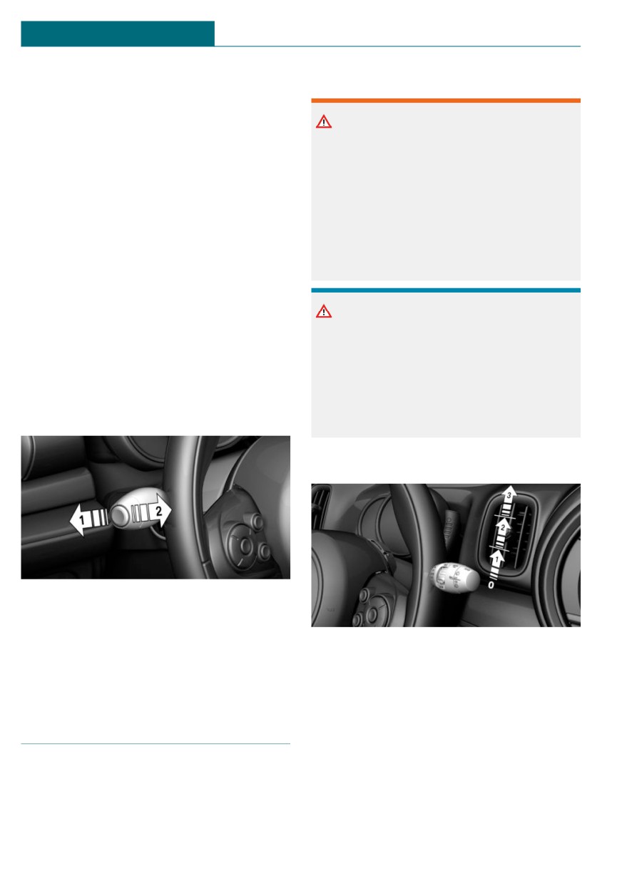
Press the lever up until the desired position
- High beams off/headlight flasher, ar-
is reached.
row 2.
- Resting position of the wipers, posi-
tion 0.
- Intermittent operation or rain sensor,
Wiper system
position 1.
- Normal wiper speed, position 2.
General information
- Fast wiper speed, position 3.
Do not use the wipers if the windshield is
dry, as this may damage the wiper blades or
cause them to become worn more quickly.
106