Dodge Grand Caravan (2020 year). Manual in english - page 11
 

  Index      Manuals     Dodge Grand Caravan (2020 year). Manual in english


Search            copyright infringement  


Content      ..     9      10      11      12     ..


Dodge Grand Caravan (2020 year). Manual in english - page 11


STARTING AND OPERATING

167

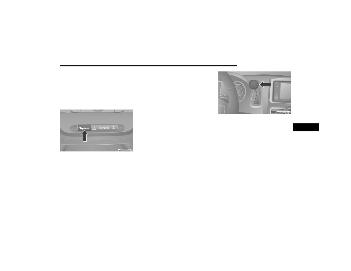
Fuel Economy (ECON) Mode

The Fuel Economy (ECON) mode can improve 

the vehicle's overall fuel economy during 

normal driving conditions. Push the “econ” 

switch in the center stack of the instrument 

panel and a green light will indicate the ECON 

mode is engaged.

Fuel Economy Mode Switch

When the Fuel Economy (ECON) Mode is 

enabled, the vehicle control systems will 

change the following:

The transmission will upshift sooner and 

downshift later.

The transmission will skip select gears during 

shifts to allow the engine to operate at lower 

speeds.

The torque converter clutch may engage at 

lower engine speeds and remain on longer.

The engine idle speed will be lower.

The overall driving performance will be more 

conservative.

Some ECON mode functions may be tempo

-

rarily inhibited based on temperature and 

other factors.

Six-Speed Automatic Transmission

The transmission gear position display (located 

in the instrument cluster) indicates the 

transmission gear range. You must press the 

brake pedal to move the gear selector out of 

PARK refer to “Brake/Transmission Shift 

Interlock System” in this section. To drive, move 

the gear selector from PARK or NEUTRAL to the 

DRIVE position.
The electronically-controlled transmission 

provides a precise shift schedule. The 

transmission electronics are self-calibrating; 

therefore, the first few shifts on a new vehicle 

may be somewhat abrupt. This is a normal 

condition, and precision shifts will develop 

within a few hundred miles (kilometers).

Gear Selector

Only shift from DRIVE to PARK or REVERSE 

when the accelerator pedal is released and the 

vehicle is stopped. Be sure to keep your foot on 

the brake pedal when shifting between these 

gears.
The transmission gear selector has only PARK, 

REVERSE, NEUTRAL, and DRIVE shift positions. 

Manual downshifts can be made using the 

Electronic Range Select (ERS) shift control refer 

to “Electronic Range Select (ERS) Operation” in 

this section for further information. Moving the 

gear selector to the left or right (–/+) while in 

the DRIVE position will select the highest 

available transmission gear, and will display 

that gear in the instrument cluster as 1, 2, 3, 

etc.

5

168

STARTING AND OPERATING


(Continued)

(Continued)

Gear Ranges

Do not depress the accelerator pedal when 

shifting from PARK or NEUTRAL into another 

gear range.

NOTE:

After selecting any gear range, wait a moment 

to allow the selected gear to engage before 

accelerating. This is especially important when 

the engine is cold.

PARK (P)

This range supplements the parking brake by 

locking the transmission. The engine can be 

started in this range. Never attempt to use 

PARK while the vehicle is in motion. Apply the 

parking brake when exiting the vehicle in this 

range.
When parking on a level surface, you may shift 

the transmission into PARK first, and then apply 

the parking brake.
When parking on a hill, apply the parking brake 

before shifting the transmission to PARK, 

otherwise the load on the transmission locking 

mechanism may make it difficult to move the 

gear selector out of PARK. As an added 

precaution, turn the front wheels toward the 

curb on a downhill grade, and away from the 

curb on an uphill grade.
When exiting the vehicle, always:

Apply the parking brake.

Shift the transmission into PARK.

Turn the engine off.

Remove the key fob.

WARNING!

It is dangerous to shift out of PARK or 

NEUTRAL if the engine speed is higher than 

idle speed. If your foot is not firmly pressing 

the brake pedal, the vehicle could accel

-

erate quickly forward or in reverse. You 

could lose control of the vehicle and hit 

someone or something. Only shift into gear 

when the engine is idling normally and your 

foot is firmly pressing the brake pedal.

Unintended movement of a vehicle could 

injure those in or near the vehicle. As with 

all vehicles, you should never exit a vehicle 

while the engine is running. Before exiting a 

vehicle, always come to a complete stop, 

then apply the parking brake, shift the 

transmission into PARK, turn the engine 

OFF, and remove the key fob. When the 

ignition is in the LOCK/OFF (key removal) 

position, the transmission is locked in 

PARK, securing the vehicle against 

unwanted movement.

When leaving the vehicle, always make 

sure the ignition is in the OFF mode, 

remove the key fob from the vehicle, and 

lock the vehicle.

Never use the PARK position as a substi

-

tute for the parking brake. Always apply the 

parking brake fully when exiting the vehicle 

to guard against vehicle movement and 

possible injury or damage.

WARNING!

 (Continued)

STARTING AND OPERATING

169

The following indicators should be used to 

ensure that you have properly engaged the 

transmission into the PARK position:

When shifting into PARK, firmly move the 

gear selector all the way forward and to the 

left until it stops and is fully seated.

Look at the transmission gear position 

display and verify that it indicates the PARK 

position (P).

With brake pedal released, verify that the 

gear selector will not move out of PARK.

REVERSE (R)

This range is for moving the vehicle backward. 

Shift into REVERSE only after the vehicle has 

come to a complete stop.

NEUTRAL (N)

Use this range when the vehicle is standing for 

prolonged periods with the engine running. The 

engine may be started in this range. Apply the 

parking brake and shift the transmission into 

PARK if you must exit the vehicle.

Your vehicle could move and injure you and 

others if it is not in PARK. Check by trying to 

move the gear selector out of PARK with the 

brake pedal released. Make sure the trans

-

mission is in PARK before exiting the 

vehicle.

Never leave children alone in a vehicle, or 

with access to an unlocked vehicle. 

Allowing children to be in a vehicle unat

-

tended is dangerous for a number of 

reasons. A child or others could be seriously 

or fatally injured. Children should be 

warned not to touch the parking brake, 

brake pedal or the transmission gear 

selector.

Do not leave the key fob in or near the 

vehicle (or in a location accessible to chil

-

dren), and do not leave the ignition in the 

ACC or ON/RUN mode. A child could 

operate power windows, other controls, or 

move the vehicle.

WARNING!

 (Continued)

CAUTION!

Before moving the transmission gear 

selector out of PARK, you must turn the igni

-

tion to the ON/RUN mode, and also press 

the brake pedal. Otherwise, damage to the 

gear selector could result.

DO NOT race the engine when shifting from 

PARK or NEUTRAL into another gear range, 

as this can damage the drivetrain.

WARNING!

Do not coast in NEUTRAL and never turn off 

the ignition to coast down a hill. These are 

unsafe practices that limit your response to 

changing traffic or road conditions. You might 

lose control of the vehicle and have a 

collision.

5

170

STARTING AND OPERATING


DRIVE (D)

This range should be used for most city and 

highway driving. It provides the smoothest 

upshifts and downshifts, and the best fuel 

economy. The transmission automatically 

upshifts through all forward gears. The DRIVE 

position provides optimum driving character

-

istics under all normal operating conditions.
When frequent transmission shifting occurs 

(such as when operating the vehicle under 

heavy loading conditions, in hilly terrain, 

traveling into strong head winds, or while towing 

a heavy trailer), use the Electronic Range Select 

(ERS) shift control refer to "Electronic Range 

Select (ERS) Operation" in this section for 

further information to select a lower gear range. 

Under these conditions, using a lower gear 

range will improve performance and extend 

transmission life by reducing excessive shifting 

and heat buildup.
During cold temperatures, transmission 

operation may be modified depending on 

engine and transmission temperature as well 

as vehicle speed. This feature improves warm 

up time of the engine and transmission to 

achieve maximum efficiency. Engagement of 

the torque converter clutch is inhibited until the 

transmission fluid is warm refer to the “Note” 

under “Torque Converter Clutch” in this section. 

During extremely cold temperatures (-16°F 

[-27°C] or below), operation may briefly be 

limited to third gear only. Normal operation will 

resume once the transmission temperature has 

risen to a suitable level.

Transmission Limp Home Mode

Transmission function is monitored electron

-

ically for abnormal conditions. If a condition is 

detected that could result in transmission 

damage, Transmission Limp Home Mode is 

activated. In this mode, the transmission 

remains in THIRD gear regardless of which 

forward gear is selected. PARK, REVERSE, and 

NEUTRAL will continue to operate. The 

Malfunction Indicator Light (MIL) may be 

illuminated. Limp Home Mode allows the 

vehicle to be driven to an authorized dealer for 

service without damaging the transmission.
In the event of a momentary problem, the 

transmission can be reset to regain all forward 

gears by performing the following steps:

1. Stop the vehicle.

2. Shift the transmission into PARK.

3. Turn the ignition OFF.

4. Wait approximately 10 seconds.

5. Restart the engine.

6. Shift into the desired gear range. If the 

problem is no longer detected, the 

transmission will return to normal 

operation.

NOTE:

Even if the transmission can be reset, we 

recommend that you visit an authorized dealer 

at your earliest possible convenience. An 

authorized dealer has diagnostic equipment to 

assess the condition of your transmission.

If the transmission cannot be reset, authorized 

dealer service is required.

CAUTION!

Towing the vehicle, coasting, or driving for any 

other reason with the transmission in 

NEUTRAL can cause severe transmission 

damage. Refer to “Recreational Towing” in 

“Starting And Operating” and “Towing A 

Disabled Vehicle” in “What To Do In 

Emergencies” for further information.

STARTING AND OPERATING

171

Electronic Range Select (ERS) Operation

The Electronic Range Select (ERS) shift control 

allows the driver to limit the highest available 

gear when the transmission is in DRIVE. For 

example, if you set the transmission gear limit 

to 4 (FOURTH gear), the transmission will not 

shift above FOURTH gear (except to prevent 

engine overspeed), but will shift through the 

lower gears normally.
You can switch between DRIVE and ERS mode 

at any vehicle speed. When the gear selector is 

in the DRIVE position, the transmission will 

operate automatically, shifting between all 

available gears. Tapping the gear selector to the 

left (-) will activate ERS mode, display the 

current gear in the instrument cluster, and set 

that gear as the top available gear. Once in ERS 

mode, tapping the gear selector to the left (-) or 

right (+) will change the top available gear.
To exit ERS mode, simply hold the gear selector 

to the right (+) until the gear limit display 

disappears from the instrument cluster.

NOTE:

To select the proper gear position for maximum deceleration (engine braking), tap the gear selector to the left (-) repeatedly as the vehicle slows. The 

transmission will shift to the range from which the vehicle can best be slowed down.

WARNING!

Do not downshift for additional engine 

braking on a slippery surface. The drive 

wheels could lose their grip and the vehicle 

could skid, causing a collision or personal 

injury.

Transmission Gear Position Display

1

2  

3

4

5

6

D

Actual Gear(s) Allowed

1

1–2

1–3

1–4

1–5

1–6

1–6

5

172

STARTING AND OPERATING


Overdrive Operation

The automatic transmission includes an 

electronically controlled Overdrive (SIXTH gear). 

The transmission will automatically shift into 

Overdrive if the following conditions are 

present:

The gear selector is in the DRIVE position.

The transmission fluid has reached an 

adequate temperature.

The engine coolant has reached an adequate 

temperature.

The vehicle speed is sufficiently high.

The driver is not heavily pressing the

accelerator.

Torque Converter Clutch

A feature designed to improve fuel economy 

has been included in the automatic 

transmission on your vehicle. A clutch within the 

torque converter engages automatically at 

calibrated speeds. This may result in a slightly 

different feeling or response during normal 

operation in the upper gears. When the vehicle 

speed drops or during some accelerations, the 

clutch automatically disengages.

NOTE:

The torque converter clutch will not engage until 

the transmission fluid and engine coolant are 

warm [usually after 1 to 3 miles (2 to 5 km) of 

driving]. Because the engine speed is higher 

when the torque converter clutch is not 

engaged, it may seem as if the transmission is 

not shifting into Overdrive when cold. This is 

normal. Using the Electronic Range Select (ERS) 

shift control, when the transmission is 

sufficiently warm, will demonstrate that the 

transmission is able to shift into and out of 

Overdrive.

POWER STEERING

The standard Power Steering system will give 

you good vehicle response and increased ease 

of maneuverability in tight spaces. The system 

will provide mechanical steering capability if 

power assist is lost.
If for some reason the power assist is 

interrupted, it will still be possible to steer your 

vehicle. Under these conditions, you will 

observe a substantial increase in steering 

effort, especially at very low vehicle speeds and 

during parking maneuvers.

NOTE:

Increased noise levels at the end of the 

steering wheel travel are considered normal 

and do not indicate that there is a problem 

with the power steering system.

Upon initial start-up in cold weather, the 

power steering pump may make noise for a 

short amount of time. This is due to the cold, 

thick fluid in the steering system. This noise 

should be considered normal, and it does not 

in any way damage the steering system.

CAUTION!

Prolonged operation of the steering system at 

the end of the steering wheel travel will 

increase the steering fluid temperature and it 

should be avoided when possible. Damage to 

the power steering pump may occur.

STARTING AND OPERATING

173

Power Steering Fluid Check

Checking the power steering fluid level at a 

defined service interval is not required. The fluid 

should only be checked if a leak is suspected, 

abnormal noises are apparent, and/or the 

system is not functioning as anticipated. 

Coordinate inspection efforts through an 

authorized dealer.

If necessary, add fluid to restore to the proper 

indicated level. With a clean cloth, wipe any 

spilled fluid from all surfaces. Refer to “Fluids 

And Lubricants” in “Technical Specifications” 

for the correct fluid type.

SPEED CONTROL — IF EQUIPPED  

When engaged, the Speed Control takes over 

accelerator operations at speeds greater than 

25 mph (40 km/h).
The Speed Control buttons are located on the 

right side of the steering wheel.

Speed Control Buttons

NOTE:

In order to ensure proper operation, the Speed 

Control System has been designed to shut down 

if multiple Speed Control functions are operated 

at the same time. If this occurs, the Speed 

Control System can be reactivated by pushing 

the Speed Control on/off button and resetting 

the desired vehicle set speed.

WARNING!

Fluid level should be checked on a level 

surface and with the engine off to prevent 

injury from moving parts and to ensure 

accurate fluid level reading. Do not overfill. 

Use only manufacturer's recommended 

power steering fluid.

CAUTION!

Do not use chemical flushes in your power 

steering system as the chemicals can 

damage your power steering components. 

Such damage is not covered by the New 

Vehicle Limited Warranty.

1 — On/Off
2 — RES (+)
3 — SET (-)
4 — CANCEL

WARNING!

Speed Control can be dangerous where the 

system cannot maintain a constant speed. 

Your vehicle could go too fast for the 

conditions, and you could lose control and 

have an accident. Do not use Speed Control 

in heavy traffic or on roads that are winding, 

icy, snow-covered or slippery.

5

174

STARTING AND OPERATING


To Activate

Push the on/off button. The Cruise Indicator 

Light in the instrument cluster display will 

illuminate. To turn the system off, push the 

on/off button a second time. The Cruise 

Indicator Light will turn off. The system should 

be turned off when not in use.

To Set A Desired Speed

Turn the Speed Control on. When the vehicle 

has reached the desired speed, push the SET (-) 

button and release. Release the accelerator 

and the vehicle will operate at the selected 

speed.

NOTE:

The vehicle should be traveling at a steady 

speed and on level ground before pushing the 

SET (-) button.

To Vary The Speed Setting

To Increase Speed
When the Speed Control is set, you can increase 

speed by pushing the RES (+) button.
The driver’s preferred units can be selected 

through the instrument panel settings (if 

equipped). Refer to “Getting To Know Your 

Instrument Panel” for more information. The 

speed increment shown is dependent on the 

chosen speed unit of U.S. (mph) or Metric

(km/h):

U.S. Speed (mph)


Pushing the RES (+) button once will result in 

a 1 mph increase in set speed. Each subse

-

quent tap of the button results in an increase 

of 1 mph.

If the button is continually pushed, the set 

speed will continue to increase until the 

button is released, then the new set speed 

will be established.

Metric Speed (km/h)


Pushing the RES (+) button once will result in 

a 1 km/h increase in set speed. Each subse

-

quent tap of the button results in an increase 

of 1 km/h.

If the button is continually pushed, the set 

speed will continue to increase until the 

button is released, then the new set speed 

will be established.

To Decrease Speed
When the Speed Control is set, you can 

decrease speed by pushing the SET (-) button.
The driver’s preferred units can be selected 

through the instrument panel settings (if 

equipped). Refer to “Getting To Know Your 

Instrument Panel” for more information. The 

speed decrement shown is dependent on the 

chosen speed unit of U.S. (mph) or Metric

(km/h):

U.S. Speed (mph)


Pushing the SET (-) button once will result in 

a 1 mph decrease in set speed. Each subse

-

quent tap of the button results in a decrease 

of 1 mph.

If the button is continually pushed, the set 

speed will continue to decrease until the 

button is released, then the new set speed 

will be established.

WARNING!

Leaving the Speed Control system on when 

not in use is dangerous. You could 

accidentally set the system or cause it to go 

faster than you want. You could lose control 

and have an accident. Always leave the 

system off when you are not using it.

STARTING AND OPERATING

175

Metric Speed (km/h)


Pushing the SET (-) button once will result in 

a 1 km/h decrease in set speed. Each subse

-

quent tap of the button results in a decrease 

of 1 km/h.

If the button is continually pushed, the set 

speed will continue to decrease until the 

button is released, then the new set speed 

will be established.

To Accelerate For Passing 

Press the accelerator as you would normally. 

When the pedal is released, the vehicle will 

return to the set speed.

Using Speed Control On Hills

The transmission may downshift on hills to 

maintain the vehicle set speed.

NOTE:

The Speed Control system maintains speed up 

and down hills. A slight speed change on 

moderate hills is normal.

On steep hills, a greater speed loss or gain may 

occur so it may be preferable to drive without 

Speed Control.

To Resume Speed

To resume a previously set speed, push the RES 

(+) button and release. Resume can be used at 

any speed above 20 mph (32 km/h).

To Deactivate

A soft tap on the brake pedal, pushing the 

CANCEL button, or normal brake pressure while 

slowing the vehicle will deactivate the Speed 

Control without erasing the set speed from 

memory.
Pushing the on/off button, or placing the 

ignition in the OFF position, erases the set 

speed from memory.

PARKSENSE REAR PARK ASSIST — IF 

EQUIPPED  

The ParkSense Rear Park Assist system 

provides visual and audible indications of the 

distance between the rear fascia and a 

detected obstacle when backing up (e.g. during 

a parking maneuver).
Refer to “ParkSense System Usage 

Precautions” in this section for limitations of 

this system and recommendations.
ParkSense will retain the last system state 

(enabled or disabled) from the last ignition cycle 

when the ignition is changed to the ON/RUN 

position.
ParkSense can be active only when the gear 

selector is in REVERSE. If ParkSense is enabled 

at this gear selector position, the system will 

remain active until the vehicle speed is 

increased to approximately 7 mph (11 km/h) or 

above. The system will become active again if 

the vehicle speed is decreased to speeds less 

than approximately 6 mph (9 km/h).

WARNING!

Speed Control can be dangerous where the 

system cannot maintain a constant speed. 

Your vehicle could go too fast for the 

conditions, and you could lose control and 

have an accident. Do not use Speed Control 

in heavy traffic or on roads that are winding, 

icy, snow-covered or slippery.

5

176

STARTING AND OPERATING


ParkSense Sensors

The four ParkSense sensors, located in the rear 

fascia/bumper, monitor the area behind the 

vehicle that is within the sensors’ field of view. 

The sensors can detect obstacles from approxi

-

mately 12 inches (30 cm) up to 79 inches

(200 cm) from the rear fascia/bumper in the 

horizontal direction, depending on the location, 

type and orientation of the obstacle.

ParkSense Warning Display

The ParkSense Warning Display is located in the 

instrument cluster display. It provides both 

visual and audible warnings to indicate the 

distance between the rear fascia/bumper and 

the detected obstacle.
The ParkSense Warning screen will only be 

displayed if Sound and Display is selected from 

the Customer-Programmable Features section 

of the instrument cluster display. Refer to 

“Instrument Cluster Display” in “Getting To 

Know Your Instrument Panel” for further 

information.

ParkSense Warning Display

ParkSense Display

When the vehicle is in REVERSE, the warning 

display will turn on indicating the system status.

Park Assist System On

Park Assist System Off

The system will indicate a detected obstacle by 

showing three solid arcs and will produce a 

one-half second tone. As the vehicle moves 

closer to the object the instrument cluster 

display will show fewer arcs and the sound tone 

will change from slow, to fast, to continuous.

Slow Tone

STARTING AND OPERATING

177

Fast Tone

Continuous Tone

The vehicle is close to the obstacle when the 

instrument cluster display shows one flashing 

arc and sounds a continuous tone. The 

following chart shows the warning alert 

operation when the system is detecting an 

obstacle:

NOTE:

ParkSense will reduce the radio volume, if on, when the system is sounding an audio tone.

WARNING ALERTS

Rear Distance 

(inches/cm)

Greater than 79 inches 

(200 cm)

79-39 inches 

(200-100 cm)

39-25 inches

(100-65 cm)

25-12 inches 

(65-30 cm)

Less than 12 inches 

(30 cm)

Audible Alert Chime

None

Single 1/2 Second 

Tone

Slow

Fast

Continuous

Arcs


None

3 Solid (Continuous)

3 Slow Flashing

2 Slow Flashing

1 Slow Flashing

Radio Volume Reduced

No

Yes

Yes

Yes

Yes

5

178

STARTING AND OPERATING


Enabling/Disabling ParkSense

ParkSense can be enabled and disabled 

through the Customer-Programmable Features 

section of the instrument cluster display. The 

available choices are: Off, Sound Only, or Sound 

and Display.
When ParkSense is disabled, the instrument 

cluster will display the “PARK ASSIST SYSTEM 

OFF” message for approximately five seconds. 

When the gear selector is moved to REVERSE 

and the system is disabled, the instrument 

cluster display will display the “PARK ASSIST 

SYSTEM OFF” message for as long as the 

vehicle is in REVERSE.
Refer to “Instrument Cluster Display” in 

“Getting To Know Your Instrument Panel” for 

further information.

Service The ParkSense Rear Park Assist 

System

During vehicle start up, when the ParkSense 

Rear Park Assist System has detected a faulted 

condition, the instrument cluster will actuate a 

single chime, once per ignition cycle, and it will 

display the “SERVICE PARK ASSIST SYSTEM” 

message. When the gear selector is moved to 

REVERSE and the system has detected a 

faulted condition, the instrument cluster display 

will display the “SERVICE PARK ASSIST 

SYSTEM” message for as long as the vehicle is 

in REVERSE. Under this condition, ParkSense 

will not operate.
Refer to “Instrument Cluster Display” in 

“Getting To Know Your Instrument Panel” for 

further information.
If “SERVICE PARK ASSIST SYSTEM” appears in 

the instrument cluster display after making sure 

the rear fascia/bumper is free from snow, ice, 

mud, dirt and debris, see an authorized dealer.

Cleaning The ParkSense System

Clean the ParkSense sensors with water, car 

wash soap and a soft cloth. Do not use rough or 

hard cloths. Do not scratch or poke the sensors. 

Otherwise, you could damage the sensors.

ParkSense System Usage Precautions

NOTE:

Ensure that the rear bumper is free of snow, 

ice, mud, dirt and debris to keep the Park

-

Sense system operating properly.

Jackhammers, large trucks, and other vibra

-

tions could affect the performance of Park

-

Sense.

When you turn ParkSense off, the instrument 

cluster will display “PARKSENSE OFF.” 

Furthermore, once you turn ParkSense off, it 

remains off until you turn it on again, even if 

you cycle the ignition.

When you move the gear selector to the 

REVERSE position and ParkSense is turned 

off, the instrument cluster display will display 

“PARKSENSE OFF” message for as long as 

the vehicle is in REVERSE.

ParkSense, when on, will reduce the volume 

of the radio when it is sounding a tone.

Clean the ParkSense sensors regularly, 

taking care not to scratch or damage them. 

The sensors must not be covered with ice, 

snow, slush, mud, dirt or debris. Failure to do 

so can result in the system not working prop

-

erly. The ParkSense system might not detect 

an obstacle behind the fascia/bumper, or it 

could provide a false indication that an 

obstacle is behind the fascia/bumper.

STARTING AND OPERATING

179

(Continued)

(Continued)

Use the ParkSense switch to turn the Park

-

Sense system off if objects such as bicycle 

carriers, trailer hitches, etc. are placed within 

12 inches (30 cm) from the rear fascia/

bumper. Failure to do so can result in the 

system misinterpreting a close object as a 

sensor problem, causing the “PARKSENSE 

UNAVAILABLE SERVICE REQUIRED” message 

to be displayed in the instrument cluster 

display.

PARKVIEW REAR BACK UP CAMERA 

Your vehicle is equipped with the ParkView Rear 

Back Up Camera that allows you to see an 

on-screen image of the rear surroundings of 

your vehicle whenever the gear selector is put 

into REVERSE. The image will be displayed on 

the touchscreen or if equipped, in the rearview 

mirror. If the image is displayed in the Uconnect 

screen, a caution note to “check entire 

surroundings” across the top of the screen. 

After five seconds this note will disappear. The 

ParkView Rear Back Up Camera is located on 

the rear of the vehicle, above the rear license 

plate.

WARNING!

Drivers must be careful when backing up 

even when using ParkSense. Always check 

carefully behind your vehicle, look behind 

you, and be sure to check for pedestrians, 

animals, other vehicles, obstructions, and 

blind spots before backing up. You are 

responsible for safety and must continue to 

pay attention to your surroundings. Failure 

to do so can result in serious injury or 

death.

Before using ParkSense, it is strongly 

recommended that the ball mount and 

hitch ball assembly is disconnected from 

the vehicle when the vehicle is not used for 

towing. Failure to do so can result in injury 

or damage to vehicles or obstacles 

because the hitch ball will be much closer 

to the obstacle than the rear fascia when 

the loudspeaker sounds the continuous 

tone. Also, the sensors could detect the ball 

mount and hitch ball assembly, depending 

on its size and shape, giving a false indica

-

tion that an obstacle is behind the vehicle.

CAUTION!

ParkSense is only a parking aid and it is 

unable to recognize every obstacle, 

including small obstacles. Parking curbs 

might be temporarily detected or not 

detected at all. Obstacles located above or 

below the sensors will not be detected 

when they are in close proximity.

WARNING!

 (Continued)

The vehicle must be driven slowly when 

using ParkSense in order to be able to stop 

in time when an obstacle is detected. It is 

recommended that the driver looks over 

his/her shoulder when using ParkSense.

CAUTION!

 (Continued)

5

180

STARTING AND OPERATING


Manual Activation Of The Rear View Camera:

1. Press the "Controls" button located on the 

bottom of the Uconnect display.

2. Press the "Backup Camera" button to turn 

the Rear View Camera system on.

When the vehicle is shifted out of REVERSE, the 

rear camera mode is exited and the last 

selected touchscreen appears again.
When the vehicle is shifted out of REVERSE 

(with Camera delay turned on), the rear Camera 

image will be displayed for up to 10 seconds 

after shifting to another gear, unless the vehicle 

speed exceeds 8 mph (13 km/h), the 

transmission is shifted into PARK, the ignition is 

placed in the OFF position, or the touchscreen 

button “X” to disable display of the Rear View 

Camera image is pressed.

NOTE:

The programmable features of the ParkView 

Rear Backup Camera can be selected through 

the touchscreen. Refer to your Uconnect 

Owner’s Manual Supplement for further 

information.

When displayed, static grid lines will illustrate 

the width of the vehicle while a dashed 

center-line will indicate the center of the vehicle 

to assist with aligning to a hitch/receiver. The 

static grid lines will show separate zones that 

will help indicate the distance to the rear of the 

vehicle. The following table shows the 

approximate distances for each zone:

NOTE:

If snow, ice, mud, or any foreign substance 

builds up on the camera lens, clean the lens, 

rinse with water, and dry with a soft cloth. Do 

not cover the lens.

Zone

Distance To The Rear 

Of The Vehicle

Red

0 - 1 ft (0 - 30 cm)

Yellow

1 ft - 3 ft (30 cm - 1 m)

Green

3 ft or greater 

(1 m or greater)

WARNING!

Drivers must be careful when backing up 

even when using the ParkView Rear Back Up 

Camera. Always check carefully behind your 

vehicle, and be sure to check for pedestrians, 

animals, other vehicles, obstructions, or blind 

spots before backing up. You are responsible 

for the safety of your surroundings and must 

continue to pay attention while backing up. 

Failure to do so can result in serious injury or 

death.

CAUTION!

To avoid vehicle damage, ParkView should 

only be used as a parking aid. The ParkView 

camera is unable to view every obstacle or 

object in your drive path.

To avoid vehicle damage, the vehicle must 

be driven slowly when using ParkView to be 

able to stop in time when an obstacle is 

seen. It is recommended that the driver 

look frequently over his/her shoulder when 

using ParkView.

STARTING AND OPERATING

181

REFUELING THE VEHICLE 

The gas cap is located behind the fuel filler door 

on the driver’s side of the vehicle. If the gas cap 

is lost or damaged, be sure the replacement 

cap is for use with this vehicle.

Fuel Filler Cap

NOTE:

The driver's side sliding door cannot be opened 

while the fuel door is open. This feature 

operates only when the sliding door is fully 

closed prior to opening the fuel door.

NOTE:

When the fuel nozzle “clicks” or shuts off, the 

fuel tank is full.

Tighten the fuel filler cap until you hear a 

“clicking” sound. This is an indication that the 

fuel filler cap is properly tightened.

If the gas cap is not tightened properly, the 

MIL may come on. Be sure the gas cap is 

tightened every time the vehicle is refueled.

Loose Fuel Filler Cap Message

If the vehicle diagnostic system determines that 

the fuel filler cap is loose, improperly installed, 

or damaged, a ”gASCAP” message will display in 

the odometer or a “Check Gascap” message will 

display in the instrument cluster. If this occurs, 

tighten the fuel filler cap properly and press the 

Trip Odometer button to turn off the message. If 

the problem continues, the message will appear 

the next time the vehicle is started.
A loose, improperly installed, or damaged fuel 

filler cap may also turn on the MIL.

CAUTION!

Damage to the fuel system or emissions 

control system could result from using an 

improper fuel tank filler tube cap. A poorly 

fitting cap could let impurities into the fuel 

system and may cause the “Malfunction 

Indicator Light (MIL)” to turn on, due to fuel 

vapors escaping from the system.

To avoid fuel spillage and overfilling, do not 

“top off” the fuel tank after filling.

WARNING!

Never have any smoking materials lit in or 

near the vehicle when the gas cap is 

removed or the tank is being filled.

Never add fuel when the engine is running. 

This is in violation of most state and federal 

fire regulations and may cause the MIL to 

turn on.

A fire may result if gasoline is pumped into 

a portable container that is inside of a 

vehicle. You could be burned. Always place 

gas containers on the ground while filling.

5

182

STARTING AND OPERATING


VEHICLE LOADING   

Certification Label

As required by National Highway Traffic Safety 

Administration regulations, your vehicle has a 

certification label affixed to the driver's side 

door or pillar.
This label contains the month and year of 

manufacture, Gross Vehicle Weight Rating 

(GVWR), Gross Axle Weight Rating (GAWR) front 

and rear, and Vehicle Identification Number 

(VIN). A Month-Day-Hour (MDH) number is 

included on this label and indicates the Month, 

Day and Hour of manufacture. The bar code 

that appears on the bottom of the label is your 

VIN.

Gross Vehicle Weight Rating (GVWR) 

The GVWR is the total permissible weight of your 

vehicle including driver, passengers, vehicle, 

options and cargo. The label also specifies 

maximum capacities of front and rear axle 

systems (GAWR). Total load must be limited so 

GVWR and front and rear GAWR are not 

exceeded.

Payload

The payload of a vehicle is defined as the 

allowable load weight a truck can carry, 

including the weight of the driver, all 

passengers, options and cargo.

Gross Axle Weight Rating (GAWR)

The GAWR is the maximum permissible load on 

the front and rear axles. The load must be 

distributed in the cargo area so that the GAWR 

of each axle is not exceeded.
Each axle GAWR is determined by the 

components in the system with the lowest load 

carrying capacity (axle, springs, tires or wheels). 

Heavier axles or suspension components 

sometimes specified by purchasers for 

increased durability does not necessarily 

increase the vehicle's GVWR.

Tire Size

The tire size on the Vehicle Certification Label 

represents the actual tire size on your vehicle. 

Replacement tires must be equal to the load 

capacity of this tire size.

Rim Size

This is the rim size that is appropriate for the tire 

size listed.

Inflation Pressure

This is the cold tire inflation pressure for your 

vehicle for all loading conditions up to full 

GAWR.

Curb Weight

The curb weight of a vehicle is defined as the 

total weight of the vehicle with all fluids, 

including vehicle fuel, at full capacity 

conditions, and with no occupants or cargo 

loaded into the vehicle. The front and rear curb 

weight values are determined by weighing your 

vehicle on a commercial scale before any 

occupants or cargo are added.

Loading

The actual total weight and the weight of the 

front and rear of your vehicle at the ground can 

best be determined by weighing it when it is 

loaded and ready for operation.


Content      ..     9      10      11      12     ..