Dodge Neon SRT (2005 year). Manual - part 4


  Index      Dodge     Dodge Neon SRT (2005 year) - manual in english


Search            copyright infringement  


Content      ..     2      3      4      5     ..


Dodge Neon SRT (2005 year). Manual - part 4


Use the hood prop rod to secure the hood in the open
position as shown. To prevent possible damage, do not
slam the hood to close it. Use a firm downward push at
the center of the hood to ensure that both latches engage.

WARNING!

If the hood is not fully latched it could fly up when
the vehicle is moving and block your forward vision.
You could have a collision. Be sure all hood latches
are fully latched before driving.
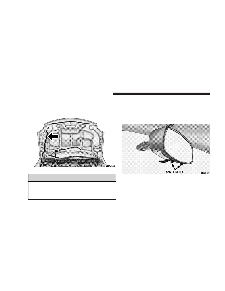
LIGHTS

Front Map/Reading Lights
These lights, located under the rearview mirror, can be
turned on by means of switches located at the base of the
rearview mirror.

NOTE:

The map lights will remain on when the ignition

switch is in the Run or Accessory positions.

Hood Prop Rod

Front Map/Reading Lights

54

UNDERSTANDING THE FEATURES OF YOUR VEHICLE

Interior Lights
The interior lights come on when a door is opened.

The interior lights will automatically turn off in about 8
minutes if a door is left open or the dimmer control is left
in the Dome light position. Turn the ignition switch ON
to restore the interior light operation.

Dimmer Control

With the park lights or headlights
on, rotating the dimmer control
for the interior lights on the Multi-
Function Control Lever upward
will increase the brightness of the
instrument panel lights.

Dome Light Position

Rotate the dimmer control com-
pletely upward to the second de-
tent to turn on the interior lights.
The interior lights will remain on
when the dimmer control is in this
position.

Daytime Brightness Feature
Certain instrument panel components can be illuminated
at full brightness during the daytime. These are the
Odometer and Radio. This can be helpful when driving
with your headlights on during the daytime such as in a
parade or a funeral procession. To activate this feature,
rotate the dimmer ring on the left stalk one detent lower
than the dome light.

UNDERSTANDING THE FEATURES OF YOUR VEHICLE

55

3

Multi-Function Control Lever
The Multi-Function Control Lever controls the operation
of the headlights, parking lights, turn signals, headlight
beam selection, instrument panel light dimming, interior
lights, the passing lights, and fog lights. The lever is
located on the left side of the steering column.

Headlights, Parking Lights, Instrument Panel
Lights
Turn the end of the Multi-Function Control Lever to the
first detent for parking light operation. Turn to the
second detent for headlight operation.

To change the brightness of the instrument panel lights,
rotate the center portion of the Multi-Function Control
Lever up or down.

Multi-Function Control Lever

56

UNDERSTANDING THE FEATURES OF YOUR VEHICLE

Daytime Running Lights (Canada Only)
The front fog lights will come on as Daytime Running
Lights whenever the ignition is on, the headlights are off,
and the parking brake is off. The headlight switch must
be used for normal night time driving.

Lights-on Reminder
If the headlights or parking lights are on after the ignition
is turned OFF, a chime will sound when the driver’s door
is opened. Leaving the headlights on for an extended
period of time will discharge the battery resulting in
reduced battery life and possible inability to start the
vehicle.

Fog Lights

The front fog light switch is on the Multi-Function
Control Lever. To activate the front fog lights, turn
on the headlights and pull out the end of the

control lever.

NOTE:

The fog lights will only operate with the head-

lights on low beam. Selecting high beam headlights or
park lights will turn off the fog lights.

Turn Signals
Move the Multi-Function Control Lever up or down to
detent and the arrows on each side of the instrument
cluster flash to show proper operation of the front and
rear turn signal lights. You can signal a lane change by
moving the lever partially up or down.

If either light remains on and does not flash, or there is a
very fast flash rate, check for a defective outside light
bulb. If an indicator fails to light when the lever is
moved, it would suggest that the fuse or indicator bulb is
defective.

Headlight Dimmer Switch
Pull the Multi-Function Control Lever towards you to
switch the headlights to HIGH beam. Pull the control
lever a second time to switch the headlights to LOW
beam.

Passing Light
You can signal another vehicle with your headlights by
lightly pulling the Multi-Function Control Lever toward
you. This will cause the headlights to turn on at high
beam and remain on until the lever is released.

UNDERSTANDING THE FEATURES OF YOUR VEHICLE

57

3

WINDSHIELD WIPERS AND WASHERS

The wipers and washers are operated by a switch
in the control lever. Move the control lever up to
select the desired wiper speed.

Windshield Washers
To use the washer, pull the control lever toward you and
hold while spray is desired. If the lever is pulled while in
the delay range, the wiper will operate in low speed for
two wipe cycles after the lever is released, and then
resume the intermittent interval previously selected.

If the lever is pulled while in the OFF position, the wipers
will operate for two wipe cycles, then turn OFF.

CAUTION!

• In cold weather, always turn off the wiper switch

and allow the wipers to return to the park position
before turning off the engine. If the wiper switch
is left on and the wipers freeze to the windshield,
damage to the wiper motor may occur when the
vehicle is restarted.

Mist Function
Push down on the wiper control lever to activate a single
wipe to clear the windshield of road mist or spray from
a passing vehicle. The wiper blade will continue to wipe
until you release the stalk.

Windshield Wiper/Washer Control

58

UNDERSTANDING THE FEATURES OF YOUR VEHICLE

Intermittent Wiper System
Use the intermittent wiper when weather conditions
make a single wiping cycle, with a variable pause be-
tween cycles, desirable. Move the lever to the first detent
(DEL) position, then select the delay interval by turning
the end of the stalk. Rotate the end upward to decrease
the delay time and downward to increase it. The delay
can be regulated from a maximum of approximately 18
seconds between cycles, to a second between cycles.

Lo Speed Wipers
Move the wiper stalk upward to the 2nd detent to obtain
a low speed wiper function.

Hi Speed Wipers
Move the wiper stalk upward to the 3rd position to
obtain the fastest wiper speed.

TILT STEERING COLUMN
To tilt the column, push down on the lever below the turn
signal control and move the wheel up or down, as
desired. Pull the lever back towards you to lock the
column firmly in place.

Tilt Steering Column Control

UNDERSTANDING THE FEATURES OF YOUR VEHICLE

59

3

WARNING!

Tilting the steering column while the vehicle is
moving is dangerous. Without a stable steering col-
umn, you could lose control of the vehicle and have
an accident. Adjust the column only while the ve-
hicle is stopped. Be sure it is locked before driving.

POWER SUNROOF — IF EQUIPPED
The sunroof control is located on the headliner between
the sun visors.

A single control “tilts” the sunroof to the vent position
and also slides the sunroof rearward to the full open
position. Move the switch rearward to move the sunroof
panel to the full vent position. The sunroof can be
stopped at any position between closed and full vent
open.

Power Sunroof Switch

60

UNDERSTANDING THE FEATURES OF YOUR VEHICLE

Once the sunroof panel is in the full vent position, you
may momentarily move the switch rearward (less than
one second) to initiate the express open mode. During
this operation, any movement of the switch will stop the
sunroof and it will remain in a partial open position.

NOTE:

When closing the sunroof, make sure the close

button is held in the close position until the motor stops.
This ensures the sunroof is fully closed and latched.

To close the sunroof, hold the switch in the forward
position. Again, any release of the switch will stop the
movement and the sunroof will remain in a partial open
condition until the switch is pushed forward again.

CAUTION!

The sunroof should not be operated above 70 mph.
Opening or closing the sunroof above 70 mph may
jam the sunroof mechanism.

WARNING!

In an accident, there is a greater risk of being thrown
from a vehicle with an open sunroof. You could also
be seriously injured or killed. Always fasten your
seat belt properly and make sure all passengers are
properly secured too.

Do not allow small children to operate the sunroof.
Never allow fingers or other body parts, or any
object to project through the sunroof opening. Injury
may result.

Sunroof Maintenance
Use only a non-abrasive cleaner and a soft cloth to clean
the glass panel.

UNDERSTANDING THE FEATURES OF YOUR VEHICLE

61

3

Wind Buffeting
Wind buffeting can be described as the perception of
pressure on the ears or a helicopter type sound in the
ears. Your vehicle may exhibit wind buffeting with the
windows down, or the sunroof (if so equipped) in certain
open or partially open positions. This is a normal occur-
rence and can be minimized. If the buffeting occurs with
the rear windows open, open the front and rear windows
together to minimize the buffeting. If the buffeting occurs
with the sunroof open, adjust the sunroof opening to
minimize the buffeting.

CONSOLE FEATURES
The Standard console with armrest has two front cup
holders and a front storage tray. There are two additional
cupholders; one is molded in the center of the console to
hold large cups, and the other is on the underside of the
console lid to serve passengers in the rear seat. The
underside console lid also has an integral tissue pack
holder. The covered storage area has CD and cassette
holders.

Front Console

62

UNDERSTANDING THE FEATURES OF YOUR VEHICLE

Ash Receiver and Cigar Lighter
When the Smoker’s Package is ordered from your autho-
rized dealer, an ash receiver tray and a cigar lighter
element are furnished. The lighter element can be in-
serted in the auxiliary power outlet. The ash receiver fits
snugly in a cupholder position. To clean the ash receiver,
lift it from the cupholder.

Ash Receiver Tray

UNDERSTANDING THE FEATURES OF YOUR VEHICLE

63

3

UNDERSTANDING YOUR INSTRUMENT PANEL

CONTENTS

䡵 Instrument Panel Features . . . . . . . . . . . . . . . .67
䡵 Instrument Cluster—Turbo . . . . . . . . . . . . . . . .68
䡵 Instrument Cluster Descriptions . . . . . . . . . . . .69
䡵 Electronic Digital Clock . . . . . . . . . . . . . . . . . .74

▫ Clock Setting Procedure . . . . . . . . . . . . . . . . . .74

䡵 Radio General Information . . . . . . . . . . . . . . . .74

▫ Radio Broadcast Signals . . . . . . . . . . . . . . . . . .74
▫ Two Types Of Signals . . . . . . . . . . . . . . . . . . .74
▫ Electrical Disturbances . . . . . . . . . . . . . . . . . . .75
▫ AM Reception . . . . . . . . . . . . . . . . . . . . . . . .75
▫ FM Reception . . . . . . . . . . . . . . . . . . . . . . . . .75

䡵 Sales Code RBK—AM/ FM Stereo Radio With

CD Player And CD Changer Controls . . . . . . . .75

▫ Radio Operation . . . . . . . . . . . . . . . . . . . . . . .75
▫ CD Player Operation . . . . . . . . . . . . . . . . . . . .77
▫ CD Changer Control Capability —

If Equipped . . . . . . . . . . . . . . . . . . . . . . . . . .79

䡵 Satellite Radio — If Equipped . . . . . . . . . . . . . .80

▫ System Activation . . . . . . . . . . . . . . . . . . . . . .80
▫ Electronic Serial Number/Sirius Identification

Number (ENS/SID) . . . . . . . . . . . . . . . . . . . . .81

▫ Selecting Satellite Mode In RBB, RAH And RBK

Radios . . . . . . . . . . . . . . . . . . . . . . . . . . . . . .81

4

▫ Selecting Satellite Mode In RBP, RBU, RAZ, RB1

And RBQ Radios . . . . . . . . . . . . . . . . . . . . . .81

▫ Selecting a Channel . . . . . . . . . . . . . . . . . . . . .82
▫ Storing And Selecting Pre-Set Channels . . . . . . .82
▫ Using The PTY (Program Type) Button

(If Equipped) . . . . . . . . . . . . . . . . . . . . . . . . .82

▫ PTY Button ⬙Scan⬙ . . . . . . . . . . . . . . . . . . . . . .82
▫ PTY Button ⬙Seek⬙ . . . . . . . . . . . . . . . . . . . . . .83
▫ Satellite Antenna . . . . . . . . . . . . . . . . . . . . . . .83

▫ Reception Quality . . . . . . . . . . . . . . . . . . . . . .83

䡵 Compact Disc Maintenance . . . . . . . . . . . . . . . .83
䡵 Radio Operation And Cellular Phones . . . . . . . .84
䡵 Climate Controls . . . . . . . . . . . . . . . . . . . . . . .84

▫ Air Conditioning . . . . . . . . . . . . . . . . . . . . . .84
▫ Operating Tips . . . . . . . . . . . . . . . . . . . . . . . .88

䡵 Electric Rear Window Defroster . . . . . . . . . . . .90
䡵 Turbo Boost Gauge . . . . . . . . . . . . . . . . . . . . . .91

66

UNDERSTANDING YOUR INSTRUMENT PANEL

INSTRUMENT PANEL FEATURES

UNDERSTANDING YOUR INSTRUMENT PANEL

67

4

INSTRUMENT CLUSTER—TURBO

68

UNDERSTANDING YOUR INSTRUMENT PANEL

INSTRUMENT CLUSTER DESCRIPTIONS

1. Fog Light Indicator

This light shows when the fog lights are ON.

2. Brake System Warning Light

This light monitors various brake functions,
including brake fluid level and parking brake
application. If the brake light comes on, it may

indicate that the parking brake is applied, or there is a
low brake fluid level. It may also indicate an ABS
malfunction that could lead to reduced braking per-
formance.

WARNING!

Driving a vehicle with the brake light on is danger-
ous. A significant decrease in braking performance
or vehicle stability during braking may occur. It will
take you longer to stop the vehicle or will make your
vehicle harder to control. You could have an acci-
dent. Have the vehicle checked immediately.

The operation of the Brake Warning light can be checked
by turning the ignition key from the OFF to the ON
position. The light should illuminate for three seconds, or
until the engine is started, whichever comes first. The
light should then go out unless the parking brake is
applied or a brake fault is detected. If the light does not
illuminate, have the light inspected and serviced as soon
as possible.

The light will also come on when the parking brake is
applied with the ignition in the ON position.

NOTE:

This light shows only that the parking brake is

on. It does not show the degree of brake application.

If the parking brake is off and the light remains on, have
the brake system inspected as soon as possible.

3. Anti-Lock Warning Light (ABS)

This light monitors the Anti-Lock Brake System
(ABS) described elsewhere in this manual. This

light will come on when the ignition key is turned to
the ON position and may stay on for as long as four
seconds.

UNDERSTANDING YOUR INSTRUMENT PANEL

69

4


Content      ..     2      3      4      5     ..