Dodge Sprinter. Manual - part 272


  Index      Dodge     Dodge Sprinter / Mercedes-Benz - service repair manual 2006 year


Search            


Content   ..  270  271  272  273   ..


Dodge Sprinter. Manual - part 272


installed. Retaining rings are available in thick-
nesses of 2.0 mm (0.079 in.), 2.1 mm (0.083 in.), and
2.2 mm (0.087 in.).

(31) Rotate the transmission so that the bellhous-

ing is pointed upward and ensuring that the output
shaft is allowed to move freely.

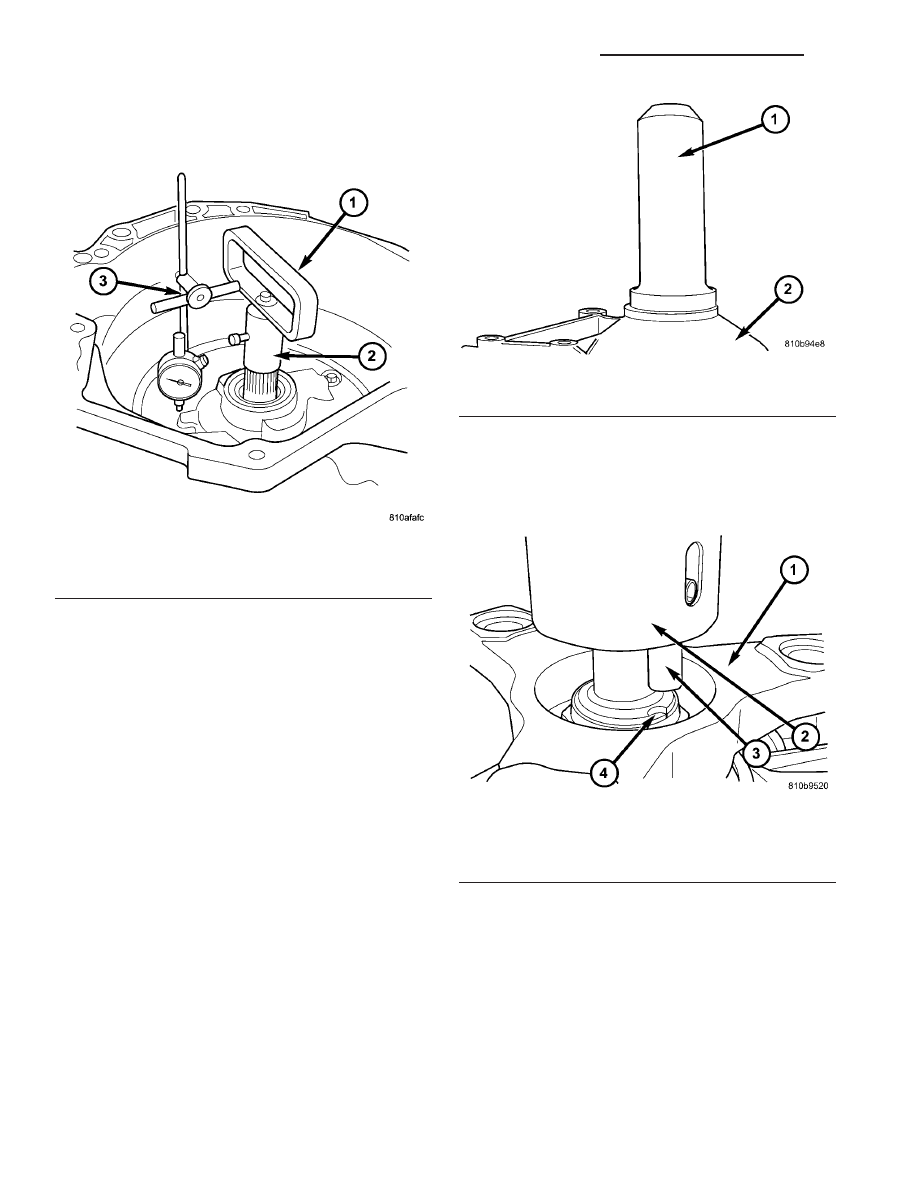
(32) Measure input shaft end-play (Fig. 58).

NOTE: If end-play is incorrect, transmission is
incorrectly assembled, or the geartrain end-play
shim is incorrect. The geartrain end-play shim is
selective.

(a) Attach Adapter 8266-18 (2) to Handle 8266-8

(1).

(b) Attach dial indicator C-3339 (3) to Handle

8266-8 (1).

(c) Install the assembled tool onto the input

shaft of the transmission and tighten the retaining
screw on Adapter 8266-18 to secure it to the input
shaft.

(d) Position the dial indicator plunger against a

flat spot on the oil pump and zero the dial indica-
tor.

(e) Move input shaft in and out and record read-

ing. End play should be 0.3-0.5 mm (0.012-0.020
in.). Adjust as necessary.

(33) Install the output shaft washer onto the out-

put shaft.

(34) Install a new transmission rear seal into the

transmission case with Seal Installer 8902A (1) (Fig.
59).

(35) Place the transmission in PARK to prepare for

the installation of the output shaft nut.

(36) Install the propeller shaft flange onto the out-

put shaft and install an new flange nut. Tighten the
flange nut to 200 N·m (147.5 ft.lbs.).

(37) Place the Staking Tool 9078 (2) and Driver

Handle C-4171 onto the output shaft.

(38) Rotate the Staking Tool 9078 (2) until the

alignment pin (3) engages the output shaft notch (4)
(Fig. 60).

Fig. 58 Checking Input Shaft End Play

1 - TOOL 8266-8
2 - TOOL 8266-18
3 - TOOL C-3339

Fig. 59 Install Output Shaft Seal

1 - SEAL INSTALLER 8902A
2 - TRANSMISSION CASE

Fig. 60 Align Staking Tool 9078

1 - PROPELLER SHAFT FLANGE
2 - STAKING TOOL 9078
3 - ALIGNMENT PIN
4 - OUTPUT SHAFT NOTCH

21 - 58

AUTOMATIC TRANSMISSION NAG1 - SERVICE INFORMATION

VA

(39) Press downward on the staking tool (1) until

the staking pin (3) contacts the output shaft nut
flange (2) (Fig. 61).

(40) Strike the Driver handle C-4171 with a suit-

able hammer until the output shaft nut is securely
staked to the output shaft.

(41) Install electrohydraulic unit (2). Tighten the

bolts to 8 N·m (71 in.lbs.).

(42) Install oil filter (4) (Fig. 62).
(43) Install oil pan (5) (Fig. 62). Tighten the bolts

to 8 N·m (71 in.lbs.).

(44) Install guide bushing (12) (Fig. 62).

Fig. 61 Stake Output Shaft Nut

1 - STAKING TOOL 9078
2 - PROPELLER FLANGE
3 - STAKING PIN

Fig. 62 Install Electrohydraulic Unit

1 - HEAT SHIELD
2 - ELECTROHYDRAULIC UNIT
3 - BOLT
4 - OIL FILTER
5 - OIL PAN
6 - CLAMPING ELEMENT
7 - BOLT
8 - DRAIN PLUG
9 - DRAIN PLUG GASKET
10 - 13-PIN PLUG CONNECTOR
11 - BOLT
12 - GUIDE BUSHING

VA

AUTOMATIC TRANSMISSION NAG1 - SERVICE INFORMATION

21 - 59

(45) Install the torque converter (Fig. 63).

INSTALLATION

(1) Coat outside of the torque converter hub with

long-term grease, install the torque converter into
the transmission.

(2) Measure distance “A” (Fig. 64) from torque con-

verter to transmission housing. If the torque con-
verter is properly installed, distance “A” will be 55
mm (2.17 in.).

(3) Move the torque converter (1) (Fig. 65) to

shown position. Check position of torque converter
through housing opening (2) when installing trans-
mission.

(4) Move driving plate (1) (Fig. 66) to shown posi-

tion.

(5) Ensure the dowel pins are installed in their

correct position at the transmission housing flange.

(6) Place transmission onto a hydraulic transmis-

sion jack and raise the transmission into position.
Secure transmission on hydraulic jack with a strap
or ask an assistant to hold it.

(7) Move the transmission into position on the

dowel pins and install two bolts (A, B) (Fig. 67) on
the top of the transmission. Torque the bolts to 38
N·m (28 ft.lbs.).

(8) Install the bolt to hose the vent hose bracket to

the transmission. Torque the bolt to 38 N·m (28
ft.lbs.).

(9) Install the bolt to hold the ground strap to the

transmission. Torque the bolt to 38 N·m (28 ft.lbs.).

Fig. 63 Install Torque Converter

1 - TORQUE CONVERTER
2 - CONVERTER HOUSING

Fig. 64 Torque Converter Installation Depth

A - TORQUE CONVERTER INSTALLED DISTANCE

Fig. 65 Position Torque Converter as Shown

1 - TORQUE CONVERTER
2 - INSPECTION OPENING

Fig. 66 Position Driveplate as Shown

1 - DRIVEPLATE

21 - 60

AUTOMATIC TRANSMISSION NAG1 - SERVICE INFORMATION

VA

(10) Install bolts (A) (Fig. 67) on underside of

transmission. Torque the bolts to 38 N·m (28 ft.lbs.).

(11) Install rear engine cross member (4) (Fig. 67).

First install the nuts (5) at the outside ends of the
engine crossmember. Then install the bolts (1) of the
transmission mount. Torque the bolts and nuts to 45
N·m (33 ft.lbs.).

(12) Remove the wooden block supporting the

engine and remove the hydraulic jack.

(13) Install the torque converter bolts.

(a) Install the first pair bolts (2) (Fig. 68) at cir-

cumference of driving plate snug only.

(b) To install bolts, position a ratchet with long

extension and joint nut as shown.

(c) Rotate engine by hand until the next pair of

bolts (2) are in front of opening. Rotate engine for-
wards at crankshaft. Install the next pair of bolts
snug only.

(d) Rotate engine by hand until the final pair of

bolts (2) are in front of opening. Rotate engine for-
wards at crankshaft. Install and torque the bolts to
50 N·m (37 ft.lbs.).

(e) Rotate engine by hand and tighten the first

two bolt pairs to 50 N·m (37 ft.lbs.).

(f) Install the plastic torque converter access

cover (1) (Fig. 69) to the back of the engine flange.

(g) Install the steering gear (1) (Fig. 70) onto the

chassis crossmember. Tighten both steering gear
bolts first to 25 N·m (18.5 ft.lbs.). Tighten both

steering gear bolts next to 45 N·m (33 ft.lbs.).
Tighten both steering gear bolts next an additional
90°.

Fig. 67 Support Transmission and Install Bolts

1 - BOLT, TRANSMISSION MOUNT
2 - UPPER SHELL FOR TRANSMISSION MOUNT
3 - TRANSMISSION MOUNT
4 - CROSSMEMBER
5 - NUT, ENGINE CROSSMEMBER
6 - NUT, TRANSMISSION SUPPORT

Fig. 68 Torque Converter Bolts

1 - BOLT
2 - STABILIZER BAR
3 - REINFORCEMENT PLATE
4 - OPENING
5 - CHASSIS CROSSMEMBER
6 - STEERING GEAR

Fig. 69 Torque Converter Access Cover

1 - TORQUE CONVERTER ACCESS COVER
2 - BOLT

VA

AUTOMATIC TRANSMISSION NAG1 - SERVICE INFORMATION

21 - 61


Content   ..  270  271  272  273   ..