Dodge Sprinter. Manual - part 247


  Index      Dodge     Dodge Sprinter / Mercedes-Benz - service repair manual 2006 year


Search            


Content   ..  245  246  247  248   ..


Dodge Sprinter. Manual - part 247


INSTALLATION

CAUTION: Whenever the fuel pump module is ser-
viced, the rubber gasket must be replaced.

(1) Thoroughly clean locknut (lockring) and lock-

nut threads at top of tank.

(2) Position new gasket (seal) to fuel tank opening.
(3) Position float rod assembly partially into fuel

tank.

(4) Position fuel pump module partially into fuel

tank.

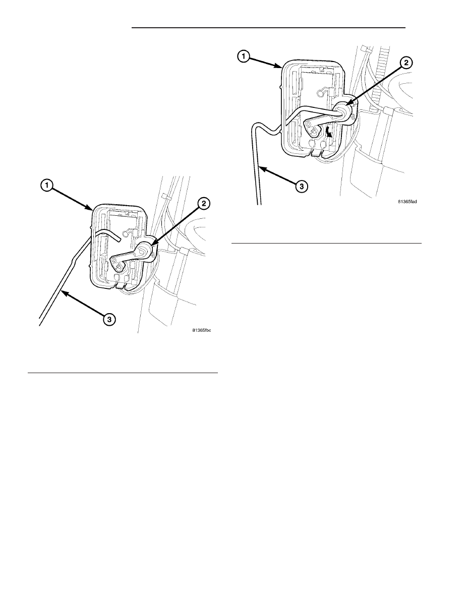
(5) Twist rod (3) (Fig. 15) into clip (2) on fuel level

sensor (1).

(6) Rotate clip (2) (Fig. 16) to attach rod (3) to

clip.

(7) After attaching float assembly to fuel level sen-

sor, carefully position fuel pump module into opening
in fuel tank.

(8) Position locknut over top of fuel pump module.

Install locknut finger tight.

(9) The fuel line fittings should be pointed to the

right side of the vehicle. Rotate and position align-
ment arrow (Fig. 17) towards right side of vehicle (if
necessary) before tightening locknut. This step
must be performed to prevent the module’s
float from contacting the side of fuel tank.

(10) Tighten locknut using Special Tool #6856.

Refer to Torque Specifications.

(11) Install fuel tank. Refer to Fuel Tank Removal/

Installation.

Fig. 15 FLOAT ROD CLIP INSTALLATION

1 - FUEL LEVEL SENSOR
2 - CLIP
3 - FLOAT ROD

Fig. 16 FLOAT ROD CLIP INSTALLATION

1 - FUEL LEVEL SENSOR
2 - CLIP
3 - FLOAT ROD

14 - 20

FUEL DELIVERY

VA

FUEL QUANTITY CONTROL
VALVE

DESCRIPTION

The fuel quantity control valve mounts to front of

the high pressure pump and is controlled by the
ECM. The quantity control valve assists in maintain-
ing proper fuel quantity injected under all operating
conditions. Fuel tank heat protection is also provided
by the quantity control valve. The valve meters the
exact amount of fuel to prevent excess heated fuel
from returning to the tank.

OPERATION

The ECM monitors the fuel system and measures

for pressure vibrations. The ECM will then send a
pulse width signal to the quantity control valve to
regulate the amount of fuel to the high pressure
pump plunger and barrel assemblies. The valve then
adjusts the injection correction quantity for each
individual cylinder in line with the firing order, there
by eliminating the pressure resonance in the fuel rail
and improving each independent injectors operation.
The fuel quantity valve also interrupts the fuel sup-
ply to the high pressure pump plunger and barrel
assemblies when the engine is switched off.

The ECM detects the operating state which exists

at the engine by means of the sensors. In order to
adapt the quantity injected, either the rail pressure
can be adjusted by way of the pressure regulator
valve and the quantity control valve, or the actuation

time of the solenoid valves in the fuel injectors can
be extended or shortened.

Fuel quantity control is performed under the fol-

lowing operating conditions:

• Approximately 30 seconds after the engine has

started

• Fuel temperature > 20°C (68°F)

• Engine not in deceleration mode

REMOVAL

(1) Disconnect the negative battery cable.
(2) Disconnect the control valve wiring harness

connector (Fig. 18).

(3) Remove the valve fasteners and remove the

control valve (Fig. 18).

INSTALLATION

(1) Clean sealing surfaces.
(2) Install new seal on sensor.
(3) Position the control valve on to the high pres-

sure pump and install fasteners (Fig. 19).

(4) Connect wiring harness connector to control

valve (Fig. 19).

(5) Connect negative battery cable.
(6) Start the engine, allow to run, turn engine off

and inspect for leaks (Refer to 14 - FUEL SYSTEM/
FUEL INJECTION - WARNING).

Fig. 17 ALIGN PUMP MODULE

1 - LOCKNUT
2 - ALIGNMENT ARROW (POSITION TOWARDS RIGHT SIDE OF
VEHICLE)

Fig. 18 HIGH PRESSURE FUEL PUMP

1 - HIGH PRESSURE PUMP
2 - FUEL SUPPY TO FUEL RAIL
3 - FUEL SUPPLY LINE
4 - FUEL RETURN LINE
5 - FUEL TEMPERATURE SENSOR
6 - FUEL QUANTITY CONTROL VALVE
7 - OIL LEVEL INDICATOR
8 - VACUUM PUMP

VA

FUEL DELIVERY

14 - 21

FUEL RAIL

DESCRIPTION

The fuel rail acts like a high pressure store. It is

available to all injectors for drawing fuel which has
been compressed by the high pressure injection
pump. The rail pressure sensor, rail pressure control
valve, high pressure line, and the return flow line
are attached to the fuel rail.

OPERATION

The stored fuel volume inside the rail acts as a

damper

for

pressure

fluctuations

which

result

because of pulsating supply and brief large extrac-
tions of fuel during injector firing. The rail primarily
influences the atomization of fuel at the injector noz-
zle, and the accuracy of injected quantity during
injection.

REMOVAL

(Refer to 14 - FUEL SYSTEM - WARNING).

WARNING: NO SPARKS, OPEN FLAMES OR SMOK-
ING. RISK OF POISONING FROM INHALING AND
SWALLOWING FUEL. RISK OF INJURY TO EYES
AND SKIN FROM CONTACT WITH FUEL. POUR
FUELS ONLY INTO SUITABLE AND APPROPRI-
ATELY MARKED CONTAINERS. WEAR PROTECTIVE
CLOTHING.

(1) Disconnect negative battery cable.
(2) Remove the engine cover.
(3) Disconnect the intake manifold air inlet duct

and position aside.

(4) Disconnect the fuel rail pressure and control

valve wiring harness connectors.

(5) Remove engine harness retaining bolts and

unclip the engine harness from the fuel rail.

(6) Remove injector high pressure lines (Fig. 19)
(7) Remove fuel rail retaining bolts (Fig. 19).

CAUTION: When slackening and tightening fuel
injection line union nuts, counter hold with wrench
at threaded connection. ON NO ACCOUNT exceed
the tightening torque at any time. Do NOT crimp or
bend lines.

NOTE: After removing lines, seal connections and
ensure cleanliness.

(8) Detach fuel return flow line to high pressure

pump at rail

(9) Detach fuel return flow line at banjo bolt (Fig.

19)

(10) Remove fuel rail.

INSTALLATION

(Refer to 14 - FUEL SYSTEM - WARNING)

WARNING: NO FIRE, FLAMES OR SMOKING. RISK
OF POISONING FROM INHALING OR SWALLOWING
FUEL. RISK OF INJURY TO EYES AND SKIN FROM
CONTACT WITH FUEL. POUR FUELS ONLY INTO
SUITABLE AND APPROPRIATELY MARKED CON-
TAINERS. WEAR PROTECTIVE CLOTHING.

(1) Loosely position fuel rail into proper position

on the cylinder head and hand tighten the fasteners.

(2) Connect the fuel pressure control valve harness

connector (Fig. 19).

(3) Connect the fuel return lines at the banjo bolt

(Fig. 19).

CAUTION: Inspect sealing cones at the lines.
Replace as necessary. Ensure that all fuel pressure
lines are exactly located in original position.

(4) Install the high pressure fuel lines and hand

tighten.

Fig. 19 FUEL RAIL

1 - CAMSHAFT POSITION SENSOR
2 - FUEL INJECTOR
3 - FUEL INJECTOR VALLEY DRAIN
4 - FUEL RAIL PRESSURE CONTROL VALVE
5 - BANJO BOLT
6 - FUEL RAIL
7 - HIGH PRESSURE FUEL LINE

14 - 22

FUEL DELIVERY

VA

(5) Tighten fuel rail bolts to 14 N·m (124 in. lbs.)

(Fig. 19)

CAUTION: When tightening fuel injection line union
nuts, counter hold with a wrench at the thread con-
nection. ON NO ACCOUNT exceed the tightening
torque at any time.

(6) Tighten the pressure line to the fuel rail to 20

N·m (177 in. lbs.).

(7) Tighten the high pressure fuel lines at the fuel

rail to 22 N·m (195 in. lbs.).

(8) Reconnect engine harness electrical connectors.
(9) Connect the intake manifold air inlet duct.
(10) Connect negative battery cable.

CAUTION: Care must be taken when installing the
engine cover. Assure the proper routing of the fuel
injector return fuel hose to the banjo bolt fitting in
the left rear corner of the cover. Failure to do so
may pinch or damage the hose causing fuel leakage
or a driveability concern.

WARNING: USE EXTREME CAUTION WHEN THE
ENGINE IS OPERATING. DO NOT STAND IN A
DIRECT LINE WITH FAN. DO NOT PUT YOUR
HANDS NEAR PULLEYS, BELTS OR FAN. DO NOT
WEAR LOOSE CLOTHING.

(11) Start engine, run for a few minutes, turn the

engine off and inspect for leaks (Refer to 14 - FUEL
SYSTEM - WARNING).

FUEL TANK

DESCRIPTION

The plastic fuel tank (Fig. 20) is mounted to the

frame rails under the left/center side of the vehicle.
The fuel tank contains a serviceable fuel pump mod-
ule with an electric fuel pump, and a fuel level send-
ing unit. The tank is also equipped with 2 fuel lines:
a fuel supply line to the fuel pump, and a separate
fuel return line.

Fuel Temperature Control: A section of the fuel

return line is coiled at the rear section of the tank
(Fig. 21). This coiled section is used to help drop the
temperature of fuel returning to the tank. A thermo-
stat (preheating valve) (3) (Fig. 21) is used to keep
fuel temperature below 167 degrees F. If fuel temper-
ature is above 167 degrees F, fuel passes first
through the coiled cooler lines, and then into the fuel
tank. If fuel temperature is below 150 degrees F, fuel
bypasses the coiled cooler lines, and is returned
directly into the fuel tank.

An electric fuel pump (more commonly referred to

in diesel applications as a fuel transfer pump or fuel
lift pump) is attached to the fuel pump module. This

module (Fig. 22) is located in the fuel tank. Refer to
Fuel Pump Module for additional information.

VA

FUEL DELIVERY

14 - 23


Content   ..  245  246  247  248   ..