Dodge Sprinter. Manual - part 18


  Index      Dodge     Dodge Sprinter / Mercedes-Benz - service repair manual 2006 year


Search            


Content   ..  16  17  18  19   ..


Dodge Sprinter. Manual - part 18


INSTALLATION

(1) Pack space between dust lip and sealing lip on

seal ring with multi-purpose grease.

(2) On seals without rubberized external surface,

coat outer circumference with sealant.

CAUTION: Do not coat partially rubberized seals
with sealant.

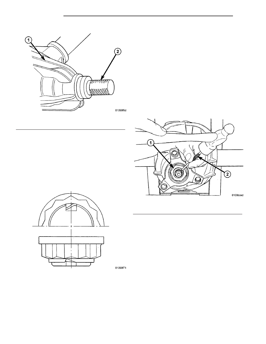
(3) Drive new pinion seal/seals into rear axle

housing as far as the stop using Installer 9276 (2)
(Fig. 60).

(4) Fit coupling flange on drive pinion shaft.

NOTE: The groove in the drive pinion and the
groove in the joint flange must be in alignment.

(5) Hold pinion flange with Flange Wrench C-3281.
(6) Tighten collar nut to 100 N·m. (74 ft. lbs.).
(7) Using a dial indicator check free play at pinion

flange.

NOTE: Should bearing not be free of play, tighten in
increases of 10 N·m. (88 in. lbs.) to maximun of 130
N·m. (95 ft. lbs.). If bearing is not free from play at
130 N·m. (95 ft. lbs.) collapsible spacer must be
replaced.

(8) Identify the position of the pinion to the nut

twevle points and mark pinion and nut.

(9) Turn nut pinion nut 30° (one twelve point).

Them rotate pinion thirty times.

(10) Measure torque to rotate. The torque to rotate

must be 0.1-0.2 N·m (0.9-1.7 in. lbs.) higher then
recorded torque.

NOTE: If value is below or above collapsible spacer
must be replaced.

(11) Cut the collar of the collared nut (Fig. 61).

(12) Bend collar nut (1) so it touches the wall of

the slot in the pinion shaft (Fig. 62).

Fig. 60 PINION SEAL INSTALLER

1 - AXLE
2 - INSTALLER

Fig. 61 COLLARED NUT

Fig. 62 BEND COLLAR OF NUT

1 - COLLARED NUT
2 - DRIFT

3 - 40

REAR AXLE

VA

(13) Connect propeller shaft to pinion flange.

NOTE: On dual rear wheel axle install axle shafts.

(14) Pour in oil up to bottom edge of oil filler hole

(1) (Fig. 63).

(15) Screw in oil filler plug (1) and tighten to 100

N·m (74 ft. lbs.).

(16) Install wheels at rear axle.
(17) Operate brake pedal several times until brake

pads contact brake discs (brake pressure built up).

(18) Attach rear brake cables if removed and

adjust parking brake.

GEAR - PINION / RING

REMOVAL

NOTE: The ring and pinion gears are serviced in a
matched set. Never replace one gear without replac-
ing the other gear.

(1) Remove differential from housing.
(2) Place differential case in a vise with soft metal

jaw.

(3) Remove ring gear bolts from the differential

case.

(4) Drive ring gear off the differential case with a

dead-blow hammer (Fig. 64).

(5) Unlock collared nut.
(6) Hold pinion flange with Flange Wrench C-3281

and remove nut.

(7) Remove pinion flange from pinion shaft with

Puller 8892 and Wrench C-3281 (Fig. 65).

(8) Remove pinion gear from housing with a dead-

blow hammer.

(9) Remove pinion shaft seal with a seal pick.
(10) Remove front pinion bearing.
(11) Remove

front

pinion

bearing

cup

with

Remover D-103 and Handle C-4171.

(12) Remove rear pinion bearing cup with Remover

9084 and Handle C-4171.

(13) Remove pinion depth shim from rear pinion

bearing cup bore.

(14) Remove collapsible spacer (Fig. 66).

Fig. 63 FILL PLUG

1 - FILL PLUG
2 - DRAIN PLUG

Fig. 64 RING GEAR

1 - CASE
2 - RING GEAR
3 - DEAD-BLOW HAMMER

Fig. 65 FLANGE PULLER

1 - FLANGE PULLER
2 - PINION FLANGE

VA

REAR AXLE

3 - 41

(15) Remove spacer from pinion shaft (Fig. 67).

(16) Remove rear bearing from pinion shaft with

Puller/Press C-293-PA and Adapters C-293-47 (Fig.
68).

INSTALLATION

(1) Apply Mopar Door Ease or equivalent lubricant

to outside surface of bearing cups.

(2) Install pinion depth shim in rear pinion bear-

ing cup bore.

(3) Install rear pinion bearing cup with Installer

C-4310 and Driver Handle C-4171.

(4) Install front pinion bearing cup with Installer

8617 and Handle C-4171.

(5) Install rear bearing on pinion with Installer

MB-998805 and a press (Fig. 69).

Fig. 66 COLLAPSIBLE SPACER

1 - COLLAPSIBLE SPACER
2 - SPACER

Fig. 67 SPACER

1 - SPACER
2 - PINION SHAFT

Fig. 68 Rear Bearing Removal

1 - PULLER
2 - VISE
3 - ADAPTERS
4 - DRIVE PINION GEAR SHAFT

3 - 42

REAR AXLE

VA

(6) Install pinion spacer on pinion shaft (Fig.

70).

(7) Install new collapsible preload spacer on pin-

ion shaft (Fig. 71) and install pinion gear into the
housing.

(8) Install front pinion bearing into housing with

Installer 9548.

(9) Apply a light coating of gear lubricant on the

lip of pinion seal and install seal with Installer 9276
(Fig. 72).

(10) Hold

pinion

flange

with

Flange

Wrench

C-3281.

(11) Screw on the new collared nut.
(12) Tighten collar nut carefully to a torque to

rotate of 2.5-3 N·m (22-27 in. lbs.).

(13) Cut the collar of the tightened collared nut

(Fig. 73).

Fig. 69 REAR BEARING INSTALLATION

1 - PRESS
2 - INSTALLER
3 - DRIVE PINION GEAR
4 - REAR PINION BEARING

Fig. 70 SPACER

1 - SPACER
2 - PINION SHAFT

Fig. 71 COLLAPSIBLE SPACER

1 - COLLAPSIBLE SPACER
2 - SPACER

Fig. 72 PINION SEAL INSTALLER

1 - AXLE
2 - INSTALLER

VA

REAR AXLE

3 - 43


Content   ..  16  17  18  19   ..