Dodge Ram Truck 1500-2500-3500. Manual - part 888
 

  Index      Dodge     Dodge Ram Truck 1500-2500-3500 - service repair manual 2005 year


Search            


Content   ..  886  887  888  889   ..


Dodge Ram Truck 1500-2500-3500. Manual - part 888


P0440-GENERAL EVAP SYSTEM FAILURE (CONTINUED)

8.

NVLD ASSEMBLY

Turn the ignition off.

Disconnect the NVLD electrical harness connector.

Check connectors - Clean/repair as necessary.

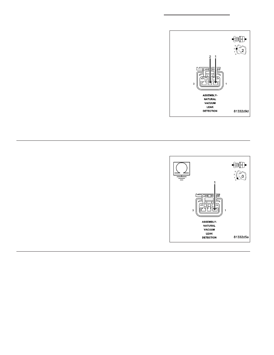
Ignition on, engine not running.

Connect a jumper wire between the (K107) NVLD Switch Signal circuit
and the (Z910) Ground circuit in the NVLD electrical harness connec-
tor.

Monitor the NVLD Switch state on the scan tool.

Does the Switch change from OPEN to CLOSED when the
jumper wire is installed?

Yes

>> Replace the NVLD Assembly.

Perform the POWERTRAIN VERIFICATION TEST. (Refer
to 9 - ENGINE - STANDARD PROCEDURE)

No

>> Go To 9

NOTE: Remove the jumper wire before continuing.

9.

(Z910) GROUND CIRCUIT OPEN

Turn the ignition off.

Measure the resistance between the (Z910) Ground circuit and
ground.

Is the resistance below 5.0 ohms?

Yes

>> Go To 10

No

>> Repair the open in the (Z910) Ground circuit.

Perform the POWERTRAIN VERIFICATION TEST. (Refer
to 9 - ENGINE - STANDARD PROCEDURE).

9 - 474

ENGINE - ELECTRICAL DIAGNOSTICS - 3.7L/4.7L/5.7L

DR/DH

P0440-GENERAL EVAP SYSTEM FAILURE (CONTINUED)

10.

(K107) NVLD SWITCH SIGNAL CIRCUIT OPEN

Disconnect the PCM harness connectors.

CAUTION: Do not probe the PCM harness connectors. Probing
the PCM harness connectors will damage the PCM terminals
resulting in poor terminal to pin connection. Install Miller Special
Tool #8815 to perform diagnosis.
Measure the resistance of the (K107) NVLD Switch Signal circuit from
the NVLD electrical harness connector to the appropriate terminal of
the special tool #8815.

Is the resistance below 5.0 ohms?

Yes

>> Go To 11

No

>> Repair the open in the (K107) Signal circuit.

Perform the POWERTRAIN VERIFICATION TEST. (Refer
to 9 - ENGINE - STANDARD PROCEDURE)

11.

PCM

NOTE: Before continuing, check the PCM harness connector terminals for corrosion, damage, or terminal
push out. Repair as necessary.
Using the schematics as a guide, inspect the wire harness and connectors. Pay particular attention to all Power and
Ground circuits.

Were there any problems found?

Yes

>> Repair as necessary.

Perform the POWERTRAIN VERIFICATION TEST. (Refer to 9 - ENGINE - STANDARD PROCEDURE)

No

>> Replace and program the Powertrain Control Module per Service Information.

Perform the POWERTRAIN VERIFICATION TEST. (Refer to 9 - ENGINE - STANDARD PROCEDURE)

DR/DH

ENGINE - ELECTRICAL DIAGNOSTICS - 3.7L/4.7L/5.7L

9 - 475

P0441-EVAP PURGE SYSTEM PERFORMANCE

9 - 476

ENGINE - ELECTRICAL DIAGNOSTICS - 3.7L/4.7L/5.7L

DR/DH

P0441-EVAP PURGE SYSTEM PERFORMANCE (CONTINUED)

For the Engine circuit diagram (Refer to 9 - ENGINE - SCHEMATICS AND DIAGRAMS).

For a complete wiring diagram Refer to Section 8W.

When Monitored:
Cold start test. Engine Running. Small Leak Test Passed.

Set Condition:
The PCM activates the EVAP Purge solenoid gradually increases to maximum flow. During flow, the PCM
looks for the NVLD switch to close. If the PCM does not see the NVLD switch close at maximum flow an error
is detected. Two Trip Fault. Three good trips to turn off the MIL.

Possible Causes

EVAP PURGE SOLENOID VACUUM SUPPLY

EVAP PURGE SOLENOID

Always perform the Pre-Diagnostic Troubleshooting procedure before proceeding. (Refer to 9 - ENGINE -
DIAGNOSIS AND TESTING).

Diagnostic Test

1.

ACTIVE DTC

NOTE: If any of the following DTCs are set (P0443, P0452, P0453, P0498 or P0499) diagnose them first
before continuing with P0441.
Ignition on, engine not running.

With a scan tool, read DTCs.

Is the DTC active at this time?

Yes

>> Go To 2

No

>> Refer to the INTERMITTENT CONDITION Diagnostic Procedure.

Perform the POWERTRAIN VERIFICATION TEST. (Refer to 9 - ENGINE - STANDARD PROCEDURE)

2.

CHECKING EVAP PURGE SOLENOID FUNCTIONALITY

NOTE: After disconnecting the Evap Purge vacuum connections, inspect the lines and solenoid for any
signs of contamination or foreign materials.
Using a hand vacuum pump, apply 10 in Hg to

9

CAN

9

side of the EVAP Purge Solenoid.

Ignition on, engine not running.

Observe the vacuum gauge.

With the scan tool, actuate the EVAP Purge Solenoid.

Does the vacuum drop when the solenoid is actuated?

Yes

>> Go To 3

No

>> Replace the Evap Purge Solenoid.

Perform the POWERTRAIN VERIFICATION TEST. (Refer to 9 - ENGINE - STANDARD PROCEDURE)

NOTE: Remove the vacuum pump before continuing.

DR/DH

ENGINE - ELECTRICAL DIAGNOSTICS - 3.7L/4.7L/5.7L

9 - 477


Content   ..  886  887  888  889   ..