Dodge Ram Truck 1500-2500-3500. Manual - part 833
 

  Index      Dodge     Dodge Ram Truck 1500-2500-3500 - service repair manual 2005 year


Search            


Content   ..  831  832  833  834   ..


Dodge Ram Truck 1500-2500-3500. Manual - part 833


P0175-FUEL SYSTEM 2/1 RICH (CONTINUED)

10.

O2 SENSOR SIGNAL CIRCUIT

WARNING: When the engine is operating, do not stand in direct
line with the fan. Do not put your hands near the pulleys, belts, or
fan. Do not wear loose clothing. Failure to follow these instruc-
tions can result in personal injury or death.
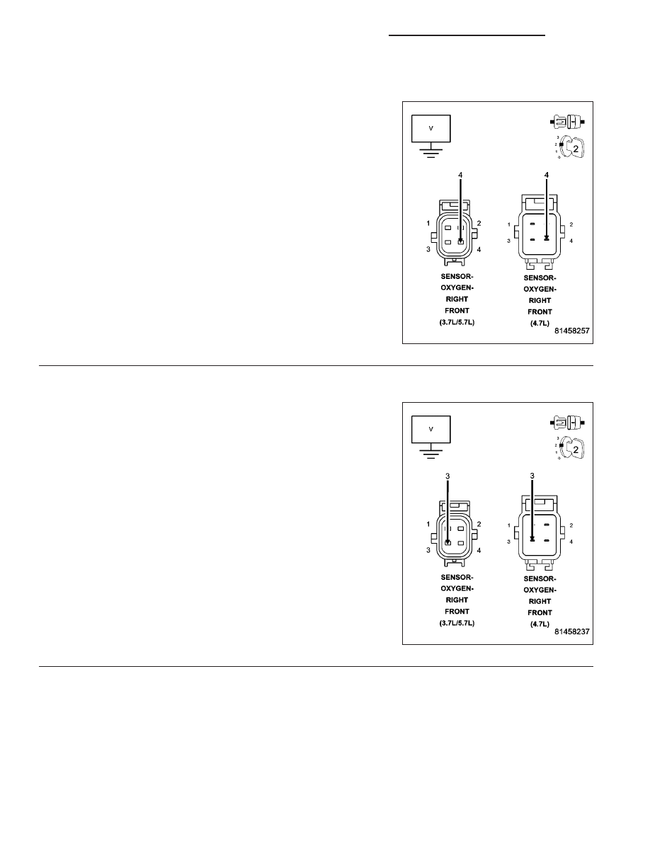
Start the engine.

Measure the voltage on the (K43) O2 Sensor 2/1 Signal circuit in the
O2 Sensor harness connector.

Is the voltage above 4.8 volts?

Yes

>> Check the (K43) O2 Sensor 2/1 Signal circuit for damage,

short to ground, open, or short to voltage. Inspect the O2
Sensor connector and the PCM harness connector. If OK,
replace and program the Powertrain Control Module per
Service Information.

Perform the POWERTRAIN VERIFICATION TEST. (Refer
to 9 - ENGINE - STANDARD PROCEDURE)

No

>> Go To 11

11.

(K902) O2 SENSOR RETURN UPSTREAM CIRCUIT

Engine still running.

Measure the voltage on the (K902) O2 Return Upstream circuit in the
O2 Sensor harness connector.

Is the voltage at 2.5 volts?

Yes

>> Go To 12

No

>> Check the (K902) O2 Return Upstream circuit for damage,

short to ground, open, or short to voltage. Inspect the O2
Sensor connector and the PCM harness connector. If OK,
replace and program the Powertrain Control Module per
Service Information.

Perform the POWERTRAIN VERIFICATION TEST. (Refer
to 9 - ENGINE - STANDARD PROCEDURE)

NOTE: Turn the ignition off before continuing.

9 - 254

ENGINE - ELECTRICAL DIAGNOSTICS - 3.7L/4.7L/5.7L

DR/DH

P0175-FUEL SYSTEM 2/1 RICH (CONTINUED)

12.

PCM

NOTE: Before continuing, check the PCM harness connector terminals for corrosion, damage, or terminal
push out. Repair as necessary.
Using the schematics as a guide, inspect the wire harness and connectors. Pay particular attention to all Power and
Ground circuits.

Were there any problems found?

Yes

>> Repair as necessary.

Perform the POWERTRAIN VERIFICATION TEST. (Refer to 9 - ENGINE - STANDARD PROCEDURE)

No

>> Replace and program the Powertrain Control Module per Service Information.

Perform the POWERTRAIN VERIFICATION TEST. (Refer to 9 - ENGINE - STANDARD PROCEDURE)

DR/DH

ENGINE - ELECTRICAL DIAGNOSTICS - 3.7L/4.7L/5.7L

9 - 255

P0201-FUEL INJECTOR 1 CIRCUIT

9 - 256

ENGINE - ELECTRICAL DIAGNOSTICS - 3.7L/4.7L/5.7L

DR/DH

P0201-FUEL INJECTOR 1 CIRCUIT (CONTINUED)

For the Engine circuit diagram (Refer to 9 - ENGINE - SCHEMATICS AND DIAGRAMS).

For a complete wiring diagram Refer to Section 8W.

When Monitored:
With battery voltage greater than 10 volts. Auto Shutdown Relay energized. Engine speed less than 3000 rpm.

Set Condition:
No inductive spike is detected after injector turn off.

Possible Causes

(K342) ASD RELAY OUTPUT CIRCUIT

(K11) INJECTOR CONTROL NO.1 CIRCUIT OPEN

(K11) INJECTOR CONTROL NO.1 CIRCUIT SHORTED TO GROUND

FUEL INJECTOR

PCM

Always perform the Pre-Diagnostic Troubleshooting procedure before proceeding. (Refer to 9 - ENGINE -
DIAGNOSIS AND TESTING).

Diagnostic Test

1.

ACTIVE DTC

Ignition on, engine not running.

With a scan tool, read DTCs.

Is the DTC active at this time?

Yes

>> Go To 2

No

>> Refer to the INTERMITTENT CONDITION Diagnostic Procedure.

Perform the POWERTRAIN VERIFICATION TEST. (Refer to 9 - ENGINE - STANDARD PROCEDURE)

2.

(K342) ASD RELAY OUTPUT CIRCUIT

Turn the ignition off.

Disconnect the No.1 Fuel Injector harness connector.

Ignition on, engine not running.

With the scan tool, actuate the ASD Relay.

Using a 12-volt test light connected to ground, probe the (K342) ASD
Relay Output circuit in the Fuel Injector harness connector.

Does the test light illuminate brightly?

Yes

>> Go To 3

No

>> Repair the excessive resistance or short to ground in the

(K342) ASD Relay Output circuit.

Perform the POWERTRAIN VERIFICATION TEST. (Refer
to 9 - ENGINE - STANDARD PROCEDURE)

DR/DH

ENGINE - ELECTRICAL DIAGNOSTICS - 3.7L/4.7L/5.7L

9 - 257


Content   ..  831  832  833  834   ..