Dodge Ram Truck 1500-2500-3500. Manual - part 436


  Index      Dodge     Dodge Ram Truck 1500-2500-3500 - service repair manual 2005 year


Search            


Content   ..  434  435  436  437   ..


Dodge Ram Truck 1500-2500-3500. Manual - part 436


LAMP - REAR FENDER

NOTE: These lamps are used on pick-up models
with dual rear wheels. A lamp with an amber lens
is located on the rear fender ahead of each rear
wheel opening, and a lamp with a red lens is
located on the rear fender behind each rear wheel
opening. The service procedures are identical for
all four of these lamps.

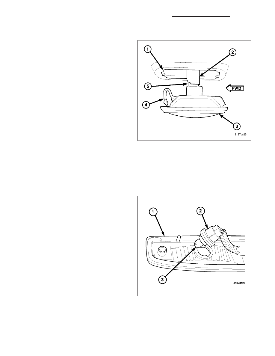
1. Position the marker lamp (3) close enough to the

mounting hole (1) to access and reconnect the wire
harness connector (2) to the bulb socket (5) on the
back of the lamp lens/housing.

2. Engage the retaining clip (4) on the front edge of

the marker lamp into the front edge of the mount-
ing hole in the rear fender.

3. Using hand pressure, press the rear edge of the

marker lamp lens/housing toward the front of the
vehicle against the spring pressure of the retaining
clip, then push the rear edge of the lamp into the
rear of the mounting hole in the rear fender.

4. Reconnect the battery negative cable.

BULB - TAILGATE

CAUTION: Always use the correct bulb size and type for replacement. An incorrect bulb size or type may
overheat and cause damage to the lamp, the socket and/or the lamp wiring.

NOTE: This lamp is used on pick-up models with
dual rear wheels. A lamp with a red lens and con-
taining three bulbs is located on the outside of the
tailgate below the tailgate latch release handle.
The bulb types and service procedures are identi-
cal for all three of these bulbs.

1. Align the base of the bulb (3) with the socket (2).

2. Push the bulb straight into the socket until the base

is firmly seated.

3. Align the socket and bulb with the keyed opening

on the back of the tailgate marker lamp lens/hous-
ing (1).

4. Insert the socket and bulb into the housing until the

socket is firmly seated.

5. Rotate the socket clockwise about 30 degrees to

lock it into place.

6. Position the marker lamp to the outer tailgate

panel.

7. Install and tighten the two screws that secure the marker lamp lens/housing to the tailgate panel. Tighten the

screws to 1 N·m (11 in. lbs.).

8. Reconnect the battery negative cable.

8L - 150

LAMPS/LIGHTING - EXTERIOR - SERVICE INFORMATION

DR/DH

LAMP - TAILGATE

NOTE: This lamp is used on pick-up models with
dual rear wheels. This lamp has a red lens, con-
tains three bulbs and is located on the outside of
the tailgate below the tailgate latch release handle.

1. Check to be certain that the two plastic nuts (1) are

properly installed and in good condition on the tail-
gate outer panel.

2. Position the marker lamp (5) close enough to the

tailgate to feed the pigtail wire (3) through the rout-
ing holes on the tailgate outer panel (2) and at the
bottom of the tailgate.

3. Position the marker lamp to the tailgate outer

panel.

4. Install and tighten the two screws that secure the

marker lamp lens/housing to the tailgate panel.
Tighten the screws to 1 N·m (11 in. lbs.).

5. Route the tailgate marker lamp (1) pigtail wire

through the routing hole in the valance panel
beneath the tailgate.

6. Reach under and behind the rear bumper near the

center to access and reconnect the tailgate marker
lamp pigtail wire connector from the wire harness
connector (2).

7. Reconnect the battery negative cable.

DR/DH

LAMPS/LIGHTING - EXTERIOR - SERVICE INFORMATION

8L - 151

SWITCH-MULTIFUNCTION

DESCRIPTION

The multi-function switch (3) is located on the steering
column, just below the steering wheel. The only visible
components of the multi-function switch are the control
stalk (2) and control knob (1) that extend through the
steering column shrouds on the left side of the col-
umn, and the hazard warning push button (4) that
extends through the shroud on the top of the column.
The remainder of the switch including its mounting
provisions, its electrical connection, and the turn signal
cancel

actuator

(5)

are

concealed

beneath

the

shrouds.

The switch housing and controls are constructed of molded black plastic. Each of the switch controls has white
International Control and Display Symbol graphics applied to it, which clearly identify its many functions. Three inte-
gral locating posts on the switch housing, one on the top and two on the bottom, slide into channels in a receptacle
on the left side of the multi-function switch mounting housing near the top of the steering column to ensure proper
positioning of the switch. Then two screws secure the switch to the mounting housing. A single integral connector
receptacle containing four terminal pins on the back of the switch housing connects the switch to the vehicle elec-
trical system through a dedicated take out and connector of the instrument panel wire harness.

The multi-function switch provides the vehicle operator with a control interface for the following functions:

Hazard Warning Control - The multi-function switch hazard warning push button provides two detent positions
(On and Off) to control the hazard warning lamps.

Headlamp Beam Selection - The multi-function switch control stalk provides detent switching for selection of
the headlamp high or low beams. There is also an intermediate momentary position that allows the headlamp
high beam circuits to be momentarily flashed to provide an optical horn feature (sometimes referred to as
flash-to-pass) as an optical signalling device.

Turn Signal Control - The multi-function switch control stalk provides momentary non-detent (lane change)
switching or detent switching with automatic cancellation for both the left and right turn signal lamps.

Washer Control - The multi-function switch control knob provides a momentary position for washer system
operation.

Wiper Control - The multi-function switch control knob provides two continuous wipe switch positions, low
speed or high speed; and, an intermittent wipe mode with five delay interval positions.

The multi-function switch cannot be adjusted or repaired. If any function of the switch is faulty, or if the switch is
damaged, the entire switch must be replaced as a unit.

OPERATION

The multi-function switch uses resistor multiplexing to control the many functions and features it provides using only
three hard wired output circuits. The switch receives a clean ground from the ElectroMechanical Instrument Cluster
(EMIC) (also sometimes referred to as the Cab Control Node/CCN) on a multi-function switch return circuit. It then
provides outputs to the EMIC on a wash/beam select switch signal circuit to control washer and headlamp beam
selection, on an intermittent wiper switch signal circuit to control wipers, and on a turn lamps switch signal circuit to
control turn signal and hazard warning functions.

The multi-function switch operates as follows:

Hazard Warning Control - The hazard warning push button of the multi-function switch is depressed to acti-
vate the hazard warning system, and depressed again to turn the system Off. When the push button is actu-
ated, the multi-function switch provides an output to the EMIC, and the EMIC responds by sending electronic
hazard switch status messages to the FCM over the PCI data bus. The FCM then energizes and flashes or
de-energizes both the left and right turn signal circuits to provide the visual hazard warning.

8L - 152

LAMPS/LIGHTING - EXTERIOR - SERVICE INFORMATION

DR/DH

Headlamp Beam Selection - The control stalk of the multi-function switch is pulled towards the steering wheel
past a detent to actuate the integral beam select switch circuitry, or to an intermediate, momentary position
before the detent to actuate the optical horn feature. Each time the control stalk is actuated to a detent posi-
tion, the opposite headlamp beam from what is currently selected will be energized. Each time the control stalk
is actuated to the momentary position with the headlamps turned off, the headlamp high beams will be illumi-
nated for as long as the control stalk is held in this position. The multi-function switch provides an output to the
EMIC, and the EMIC responds by sending electronic beam select switch status messages to the FCM over the
PCI data bus. The FCM energizes or de-energizes the selected low or high beam circuits.

Turn Signal Control - The control stalk of the multi-function switch is moved upward to activate the right turn
signal circuitry, and, downward to activate the left turn signal circuitry. The turn signal switch has a detent
position in each direction that provides turn signals with automatic cancellation, and an intermediate, momen-
tary position in each direction that provides turn signals only until the control stalk is released. When the con-
trol stalk is moved to a detent turn signal switch position, the cancel actuator extends toward the center of the
steering column. A turn signal cancel cam that is integral to the clockspring rotates with the steering wheel and
the cam lobes contact the cancel actuator when it is extended from the multi-function switch. When the steer-
ing wheel is rotated during a turning maneuver, one of the two turn signal cancel cam lobes will contact the
turn signal cancel actuator. The cancel actuator latches against the cancel cam rotation in the direction oppo-
site that which is signaled. If the left turn signal detent is selected, the lobes of the cancel cam will ratchet past
the cancel actuator when the steering wheel is rotated to the left, but will unlatch the cancel actuator as the
steering wheel rotates to the right and returns to center, which will cancel the turn signal event and release the
control stalk from the detent so it returns to the neutral Off position. When a turn signal is activated, the multi-
function switch provides an output to the EMIC, and the EMIC responds by sending electronic turn signal
switch status messages to the FCM over the PCI data bus. The FCM energizes and flashes or de-energizes
the selected left or right turn signal circuits.

Washer Control - The control knob on the end of the multi-function switch control stalk is depressed towards
the steering column to momentarily activate the washer pump in the washer mode. The washer pump will
continue to operate in the washer mode until the control knob is released. The multi-function switch provides
an output to the EMIC, and the EMIC responds by sending electronic washer switch status messages to the
Front Control Module (FCM) over the Programmable Communications Interface (PCI) data bus. The FCM
responds by energizing or de-energizing the washer pump in the washer mode.

Wiper Control - The control knob on the end of the multi-function switch control stalk is rotated to one of the
continuous wiper detents, to one of five intermittent wiper detents, or to the Off position to select the wiper
mode. The multi-function switch provides an output to the EMIC, and the EMIC responds by sending electronic
wiper switch status messages to the FCM over the PCI data bus. The FCM responds by energizing or de-
energizing the wiper on/off and high/low relays in the Power Distribution Center (PDC) for wiper system con-
trol.

The multi-function switch can be diagnosed using conventional diagnostic tools and methods. However, proper test-
ing of the multiplexed inputs to the EMIC requires the use of a diagnostic scan tool. Refer to the appropriate diag-
nostic information.

DIAGNOSIS AND TESTING

MULTI-FUNCTION SWITCH

WARNING: To avoid personal injury or death, on vehicles equipped with airbags, disable the supplemental
restraint system before attempting any steering wheel, steering column, airbag, seat belt tensioner, impact
sensor, or instrument panel component diagnosis or service. Disconnect and isolate the battery negative
(ground) cable, then wait two minutes for the system capacitor to discharge before performing further diag-
nosis or service. This is the only sure way to disable the supplemental restraint system. Failure to take the
proper precautions could result in accidental airbag deployment.

DR/DH

LAMPS/LIGHTING - EXTERIOR - SERVICE INFORMATION

8L - 153


Content   ..  434  435  436  437   ..