Content .. 2076 2077 2078 2079 ..
Dodge Ram Truck 1500-2500-3500. Manual - part 2078
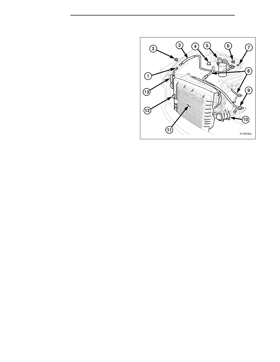
REAR SECTION
1. Recover the refrigerant from the refrigerant system
(Refer to 24 - HEATING & AIR CONDITIONING/
PLUMBING
-
STANDARD
PROCEDURE
-
REFRIGERANT SYSTEM RECOVERY).
2. Disconnect and isolate the negative battery cable.
3. Remove the air filter housing (Refer to 9 -
ENGINE/AIR
INTAKE
SYSTEM/AIR
FILTER
HOUSING - REMOVAL).
4. Remove the secondary retaining clip (2) from the
spring-lock coupler that secures the front section of
the A/C liquid line (1) to the rear section of the liq-
uid line (3).
5. Disengage the A/C liquid line from the body retain-
ing clips.
6. Using the proper A/C line disconnect tool, discon-
nect the front section of the A/C liquid line from the
rear section of the liquid line and remove and dis-
card the seal (Refer to 24 - HEATING & AIR CON-
DITIONING/PLUMBING/COUPLER-REFRIGERANT LINE - REMOVAL).
7. Remove the secondary retaining clip (6) from the spring-lock coupler that secures the rear section of the A/C
liquid line to the evaporator inlet tube (7).
8. Using the proper A/C line disconnect tool, disconnect the A/C liquid line from the evaporator inlet tube and
remove and discard the seal (Refer to 24 - HEATING & AIR CONDITIONING/PLUMBING/COUPLER-REFRIG-
ERANT LINE - REMOVAL).
9. Install plugs in, or tape over the opened ends of the A/C liquid lines and the evaporator inlet port.
10. Remove the rear section of the A/C liquid line from the engine compartment.
INSTALLATION
3.7L/4.7L/5.7L/5.9L ENGINES
NOTE: The A/C liquid line is serviced in two sections.
24 - 312
PLUMBING
DR/DH