Dodge Ram Truck 1500-2500-3500. Manual - part 2065


  Index      Dodge     Dodge Ram Truck 1500-2500-3500 - service repair manual 2005 year


Search            


Content   ..  2063  2064  2065  2066   ..


Dodge Ram Truck 1500-2500-3500. Manual - part 2065
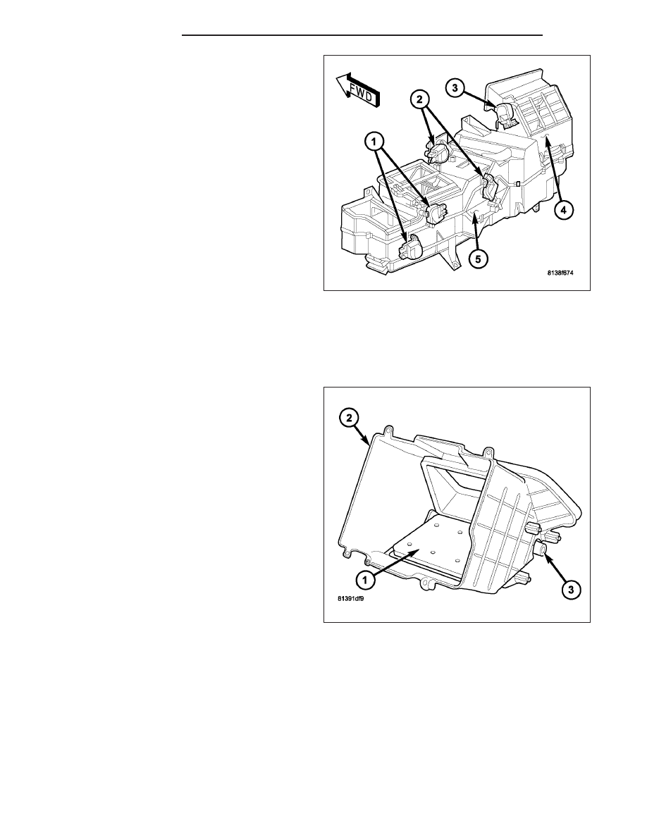


34. Position the recirculation door actuator (3) onto

the air inlet housing (4) and install the retaining
screws. Tighten the screws to 2.2 N·m (20 in.
lbs.).

35. Position the mode door actuators (1) and the

blend door actuators (2) onto the HVAC housing
(5) and install the retaining screws. Tighten the
screws to 2.2 N·m (20 in. lbs.).

36. Connect the HVAC wire harness connectors to the

actuators.

37. Install the HVAC housing assembly (Refer to 24 -

HEATING & AIR CONDITIONING/DISTRIBUTION/
HOUSING-HVAC - HVAC HOUSING ASSEMBLY -
INSTALLATION).

AIR INLET HOUSING

NOTE: The air inlet housing must be removed from HVAC housing and disassembled for service of the
recirculation-air door.

NOTE: If the seals on the air door is deformed or
damaged, the air door must be replaced.

1. Position the recirculation-air door (1) into the air

inlet housing (2).

CAUTION: Make sure that the recirculation-air
door pivot shaft is properly seated in the pivot
seat located in the air inlet housing.

2. Align the actuator coupler (3) with the recirculation-

air door pivot shaft and install the coupler until the
coupler retaining tabs are fully engaged to the air
inlet housing. Be sure to install the coupler with the
coupler arm located between the two stop tabs on
the air inlet housing.

24 - 260

DISTRIBUTION

DR/DH

3. Install the two foam insulators (2) into the air inlet

housing (1).

4. Install the air inlet housing onto the HVAC housing

(Refer to 24 - HEATING & AIR CONDITIONING/
DISTRIBUTION/HOUSING-HVAC

-

AIR

INLET

HOUSING - INSTALLATION).

INSTALLATION

HVAC HOUSING ASSEMBLY

NOTE: The HVAC housing must be removed from the vehicle and disassembled for service of the A/C evap-
orator, evaporator temperature sensor, mode-air and blend-air doors.

1. If removed, install the fresh air inlet (2) onto the

dash panel (1).

2. Position the HVAC housing assembly (4) into the

passenger compartment with the mounting studs
and the condensate drain tube in their proper loca-
tions in the dash panel.

3. Install the two nuts (3 and 7) that secure the HVAC

housing to the passenger compartment side of the
dash panel. Tighten the nuts to 6.2 N·m (55 in.
lbs.).

4. Install the bolt (5) that secures the HVAC housing

to the floor bracket (6). Tighten the bolt to 6.2 N·m
(55 in. lbs.).

5. Install the instrument panel (Refer to 23 - BODY/

INSTRUMENT

PANEL

ASSEMBLY

-

INSTALLATION).

DR/DH

DISTRIBUTION

24 - 261

6. Install the two nuts (3) that secure the HVAC hous-

ing (1) to the engine compartment side of the dash
panel (2). Tighten the nuts to 6.2 N·m (55 in. lbs.).

7. Install the powertrain control module (PCM) (Refer

to

8

-

ELECTRICAL/ELECTRONIC

CONTROL

MODULES/POWERTRAIN CONTROL MODULE -
INSTALLATION).

8. Connect the heater hoses to the heater core tubes.

9. Connect the A/C liquid line and the A/C accumula-

tor to the A/C evaporator (Refer to 24 - HEATING &
AIR CONDITIONING/PLUMBING /LINE-A/C LIQ-
UID - INSTALLATION) and (Refer to 24 - HEATING
& AIR CONDITIONING/PLUMBING/ACCUMULA-
TOR-A/C - INSTALLATION).

10. Reconnect the negative battery cable.

11. If the heater core is being replaced, flush the cool-

ing system (Refer to 7 - COOLING - STANDARD
PROCEDURE - COOLING SYSTEM CLEANING/
REVERSE FLUSHING).

12. Refill the engine cooling system (Refer to 7 - COOLING - STANDARD PROCEDURE - COOLING SYSTEM

REFILL).

13. Evacuate the refrigerant system (Refer to 24 - HEATING & AIR CONDITIONING/PLUMBING - STANDARD

PROCEDURE - REFRIGERANT SYSTEM EVACUATE).

14. Charge the refrigerant system (Refer to 24 - HEATING & AIR CONDITIONING/PLUMBING - STANDARD PRO-

CEDURE - REFRIGERANT SYSTEM CHARGE).

AIR INLET HOUSING

NOTE: The air inlet housing must be removed from HVAC housing and disassembled for service of the
recirculation-air door.

NOTE: If the foam seal on the air inlet housing is
deformed or damaged, it must be replaced.

1. Position the air inlet housing (2) onto the top of the

HVAC housing (3).

2. Engage the two retaining clips (1) that secure the

front of the air inlet housing to the HVAC housing.

24 - 262

DISTRIBUTION

DR/DH

3. Install the two screws (3) that secure the rear of

the air inlet housing (2) to the top of the HVAC
housing (5). Tighten the screws to 2.2 N·m (20 in.
lbs.).

4. Install the recirculation door actuator (1) onto the

air inlet housing (Refer to 24 - HEATING & AIR
CONDITIONING/CONTROLS/ACTUATOR-RECIR-
CULATION DOOR - INSTALLATION).

5. Connect the HVAC wire harness (4) to the recircu-

lation door actuator.

6. Install the HVAC housing assembly (Refer to 24 -

HEATING & AIR CONDITIONING/DISTRIBUTION/
HOUSING-HVAC - HVAC HOUSING ASSEMBLY -
INSTALLATION).

MOTOR-BLOWER

DESCRIPTION

The blower motor (1) is a 12-volt, direct current (DC)
motor mounted within a plastic housing with an inte-
gral wire harness connector (2) and squirrel cage-type
blower wheel (3) that is secured to the blower motor
shaft (4). The blower motor wheel is located in the
HVAC air inlet housing which is mounted to the pas-
senger side end of the HVAC housing. The blower
motor can be accessed for service from underneath
the instrument panel.

OPERATION

The blower motor is used to control the velocity of air moving through the HVAC housing by spinning the blower
wheel within the HVAC air inlet housing at the selected speed.

The blower motor will operate whenever the ignition switch is in the On position and the blower motor control in any
position except Off. The blower motor receives a fused battery feed circuit through a fuse in the power distribution
center (PDC) whenever the ignition switch is in the On position.

Blower motor speed is controlled by regulating the ground path through or around the blower motor resistor block
and through the blower motor control located within the A/C-heater control.

DR/DH

DISTRIBUTION

24 - 263


Content   ..  2063  2064  2065  2066   ..