Content .. 1817 1818 1819 1820 ..
Dodge Ram Truck 1500-2500-3500. Manual - part 1819
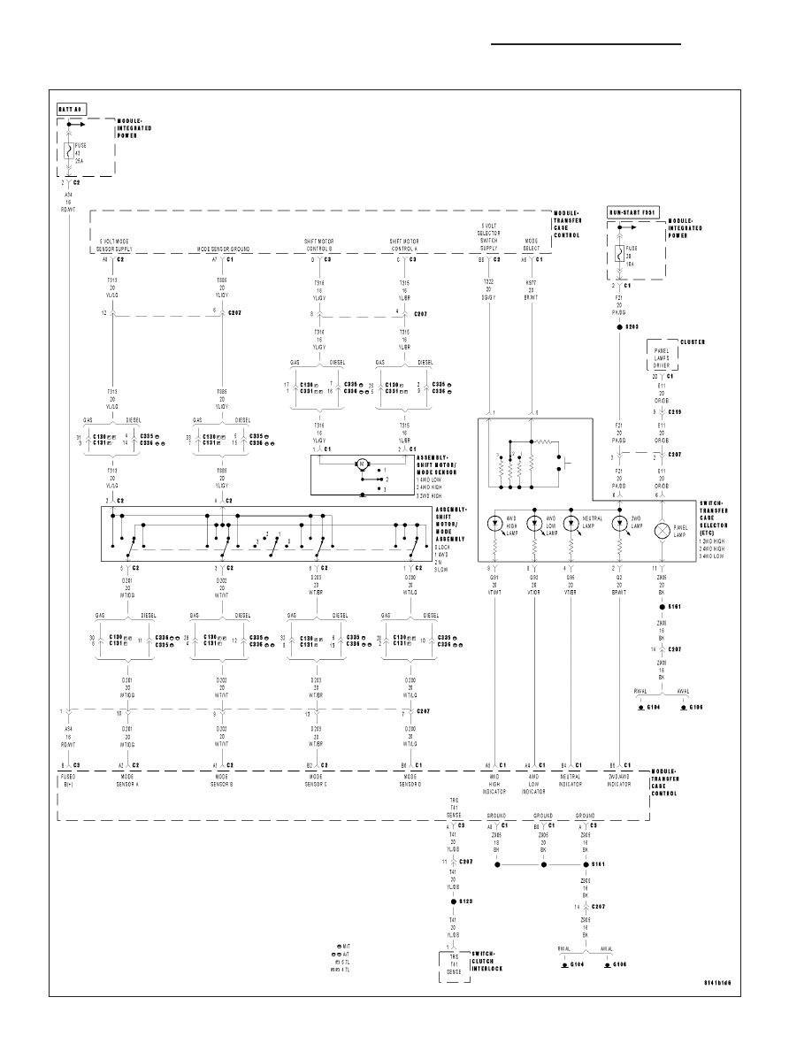
2WD/AWD INDICATOR SHORTED
21 - 1208
TRANSFER CASE - ELECTRICAL DIAGNOSTICS (ETC)
DR/DH
|
|
|
Content .. 1817 1818 1819 1820 ..
2WD/AWD INDICATOR SHORTED 21 - 1208 TRANSFER CASE - ELECTRICAL DIAGNOSTICS (ETC) DR/DH |