Content .. 1455 1456 1457 1458 ..
Dodge Ram Truck 1500-2500-3500. Manual - part 1457
MODULE - FUEL PUMP
DESCRIPTION
The fuel pump module assembly is located on the top of the fuel tank. The complete assembly contains the fol-
lowing components:
•
A combination fuel filter/fuel pressure regulator
•
A separate fuel pick-up, or inlet filter
•
An electric fuel pump
•
A lockring to retain pump module to tank
•
A soft gasket between tank flange and module
•
A fuel gauge sending unit (fuel level sensor)
•
Fuel line connection
The fuel gauge sending unit may be serviced separately. If the electrical fuel pump, primary inlet filter, fuel filter or
fuel pressure regulator require service, the fuel pump module must be replaced.
OPERATION
Refer to Fuel Pump, Inlet Filter, Fuel Filter / Fuel Pressure Regulator and Fuel Gauge Sending Unit.
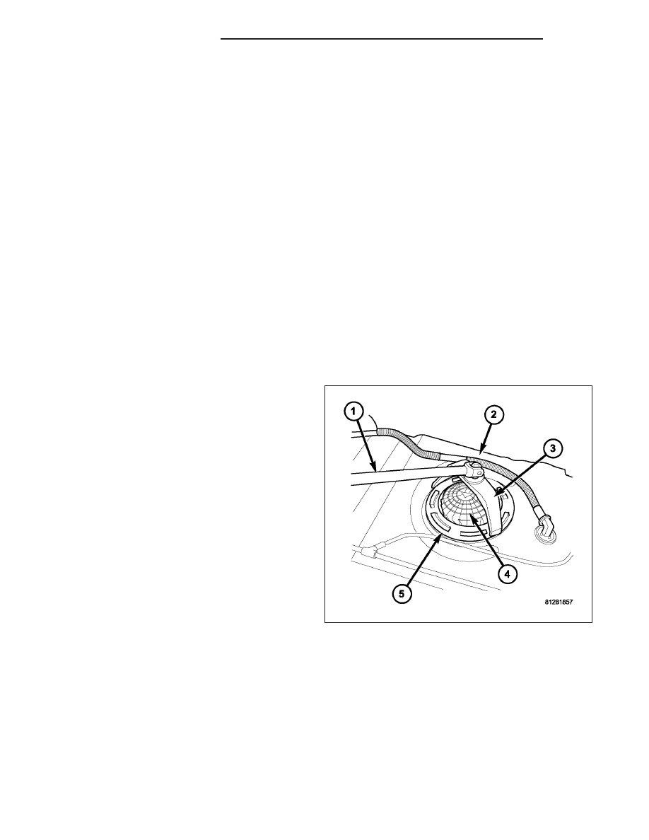
REMOVAL
WARNING: THE FUEL SYSTEM MAY BE UNDER A CONSTANT PRESSURE (EVEN WITH THE ENGINE OFF).
BEFORE SERVICING THE FUEL PUMP MODULE, THE FUEL SYSTEM PRESSURE MUST BE RELEASED.
1. Drain and remove fuel tank. Refer to Fuel Tank
Removal/Installation.
2. Note rotational position of module before attempt-
ing removal. An indexing arrow is located on top of
module for this purpose.
3. Position Special Tool 9340 (3) into notches on out-
side edge of lockring (5).
4. Install 1/2 inch drive breaker bar (1) to tool 9340
(3).
5. Rotate breaker bar counter-clockwise to remove
lockring (5).
6. Remove lockring. The module will spring up slightly
when lockring is removed.
7. Remove module from fuel tank. Be careful not to
bend float arm while removing.
14 - 16
FUEL DELIVERY - GAS
DR/DH