Dodge Ram Truck 1500-2500-3500. Manual - part 1296


  Index      Dodge     Dodge Ram Truck 1500-2500-3500 - service repair manual 2005 year


Search            


Content   ..  1294  1295  1296  1297   ..


Dodge Ram Truck 1500-2500-3500. Manual - part 1296


CAUTION: Use extreme caution when crankshaft polishing is necessary to remove minor nicks or
scratches. The crankshaft seal flange is specially machined to complement the function of the rear oil seal.

6. For bubbles that remain steady with shaft rotation, no further inspection can be done until disassembled. (Refer

to 9 - ENGINE - DIAGNOSIS AND TESTING), under the Oil Leak row, for components inspections on possible
causes and corrections.

7. After the oil leak root cause and appropriate corrective action have been identified, (Refer to 9 - ENGINE/EN-

GINE BLOCK/CRANKSHAFT OIL SEAL - REAR - REMOVAL).

REMOVAL

NOTE: This procedure can be performed in vehi-
cle.

1. If being performed in vehicle, remove the transmis-

sion.

2. Remove the flexplate (Refer to 9 - ENGINE/EN-

GINE BLOCK/FLEX PLATE - REMOVAL).

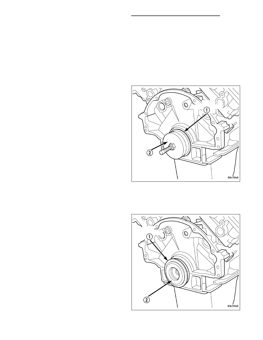
NOTE: The crankshaft oil seal CAN NOT be reused
after removal.

NOTE: The crankshaft rear oil seal remover Spe-
cial Tool 8506 must be installed deeply into the
seal. Continue to tighten the removal tool into the
seal until the tool can not be turned farther. Fail-
ure to install tool correctly the first time will cause
tool to pull free of seal without removing seal from
engine.

3. Using Special Tool 8506 (2), remove the crankshaft rear oil seal (1)

INSTALLATION

1. Lubricate the crankshaft flange with engine oil.

2. Position the magnetic seal guide Special Tool

8349-2 onto the crankshaft rear face. Then position
the crankshaft rear oil seal (1) onto the guide (2).

9 - 2106

ENGINE - 3.7L - SERVICE INFORMATION

DR/DH

3. Using Special Tools 8349 Crankshaft Rear Oil Seal

Installer (2) and C-4171 Driver Handle (3), with a
hammer, tap the seal (1) into place. Continue to
tap on the driver handle until the seal installer
seats against the cylinder block crankshaft bore.

4. Install the flexplate.

5. Install the transmission.

FLEX PLATE

REMOVAL

1. Remove the transmission. (Refer to 21 - TRANS-

MISSION/TRANSAXLE/AUTOMATIC

-

45RFE/

545RFE - REMOVAL).

2. Remove the bolts and flexplate (1).

DR/DH

ENGINE - 3.7L - SERVICE INFORMATION

9 - 2107

INSTALLATION

1. Position the flexplate onto the crankshaft and install

the bolts hand tight.

2. Tighten the flexplate (1) retaining bolts to 95 N·m

(70 ft. lbs.) in the sequence shown.

3. Install the transmission.

PISTON & CONNECTING ROD

DESCRIPTION

CAUTION: Do not use a metal stamp to mark con-
necting rods as damage may result, instead use
ink or a scratch awl.

The pistons (2) are made of a high strength aluminum
alloy. The connecting rods (1) are made of forged
powdered metal, with a “fractured cap” design. A full
floating piston pin is used to attach the piston to the
connecting rod.

9 - 2108

ENGINE - 3.7L - SERVICE INFORMATION

DR/DH

STANDARD PROCEDURE

CONNECTING ROD BEARING FITTING

Inspect the connecting rod bearings for scoring. Check
the bearings for normal wear patterns, scoring, groov-
ing, fatigue and pitting. Replace any bearing that
shows abnormal wear.

Inspect the connecting rod journals for signs of scor-
ing, nicks and burrs.

Misaligned or bent connecting rods can cause abnor-
mal wear on pistons, piston rings, cylinder walls, con-
necting rod bearings and crankshaft connecting rod
journals. If wear patterns or damage to any of these
components indicate the probability of a misaligned
connecting rod, inspect it for correct rod alignment.
Replace misaligned, bent or twisted connecting rods.

1. Wipe the oil from the connecting rod journal.

2. Lubricate the upper bearing insert and position in

connecting rod. Center bearing insert (2) in con-
necting rod (1)

DR/DH

ENGINE - 3.7L - SERVICE INFORMATION

9 - 2109


Content   ..  1294  1295  1296  1297   ..