Content .. 1291 1292 1293 1294 ..
Dodge Ram Truck 1500-2500-3500. Manual - part 1293
REMOVAL
NOTE: Disconnect the battery negative cable to
prevent accidental starter engagement.
1. Remove the cylinder head cover (Refer to 9 -
ENGINE/CYLINDER
HEAD/CYLINDER
HEAD
COVER(S) - REMOVAL).
2. For rocker arm removal on cylinder No. 4, Rotate
the crankshaft until cylinder No. 1 is at BDC intake
stroke.
3. For rocker arm removal on cylinder No. 1, Rotate
the crankshaft until cylinder No. 1 is at BDC com-
bustion stroke.
4. For rocker arm removal on cylinders No. 3 and No.
5, Rotate the crankshaft until cylinder No. 1 is at
TDC exhaust stroke.
5. For rocker arm removal on cylinders No. 2 and No.
6, Rotate the crankshaft until cylinder No. 1 is at
TDC ignition stroke.
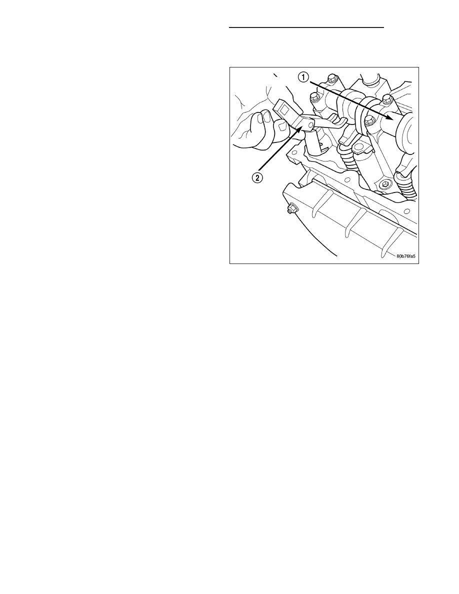
6. Using special tool 8516 Rocker Arm Remover (2) ,
press downward on the valve spring, remove
rocker arm.
SEALS - VALVE GUIDE
DESCRIPTION
The valve guide seals are made of rubber and incorporate an integral steel valve spring seat. The integral garter
spring maintains consistent lubrication control to the valve stems.
SPRINGS - VALVE
DESCRIPTION
The valve springs are made from high strength chrome silicon steel. There are different springs for intake and
exhaust applications. The exhaust spring has an external damper. The valve spring seat is integral with the valve
stem seal, which is a positive type seal to control lubrication.
REMOVAL
1. Remove the cylinder head cover (Refer to 9 - ENGINE/CYLINDER HEAD/CYLINDER HEAD COVER(S) -
REMOVAL).
2. Using Special Tool 8516 Valve Spring Compressor, remove the rocker arms and the hydraulic lash adjusters.
3. Remove the spark plug for the cylinder the valve spring and seal are to be removed from.
4. Apply shop air to the cylinder to hold the valves in place when the spring is removed.
NOTE: All six valve springs and seals are removed in the same manner; this procedure only covers one
valve seal and valve spring.
5. Using Special Tool 8387 Valve Spring Compressor, compress the valve spring.
NOTE: It may be necessary to tap the top of the valve spring to loosen the spring retainers locks enough to
be removed.
9 - 2094
ENGINE - 3.7L - SERVICE INFORMATION
DR/DH