Content .. 1207 1208 1209 1210 ..
Dodge Ram Truck 1500-2500-3500. Manual - part 1209
P0304-CYLINDER #4 MISFIRE (CONTINUED)
13.
FUEL PUMP INLET STRAINER
Turn the ignition off.
WARNING: The fuel system is under a constant pressure (even with the engine off). Before testing or ser-
vicing any fuel system hose, fitting or line, the fuel system pressure must be released. Failure to follow
these instructions can result in personal injury or death.
Remove the Fuel Pump Module and inspect the Fuel Inlet Strainer.
Is the Fuel Inlet Strainer plugged?
Yes
>> Replace the Fuel Pump Inlet Strainer.
Perform the POWERTRAIN VERIFICATION TEST. (Refer to 9 - ENGINE - STANDARD PROCEDURE)
No
>> Before continuing, check the Fuel Pump Module harness connector terminals for corrosion, damage, or
terminal push out. Make sure the ground circuit is functional. Repair as necessary. Replace the Fuel
Pump Module.
Perform the POWERTRAIN VERIFICATION TEST. (Refer to 9 - ENGINE - STANDARD PROCEDURE)
14.
IGNITION WIRE
NOTE: If the vehicle being tested does not have an ignition wire answer YES to this test and continue.
Turn the ignition off.
Remove the ignition wire.
Measure the resistance of the ignition wire.
Is the resistance below 10K ohms?
Yes
>> Go To 15
No
>> Replace the Ignition Wire.
Perform the POWERTRAIN VERIFICATION TEST. (Refer to 9 - ENGINE - STANDARD PROCEDURE)
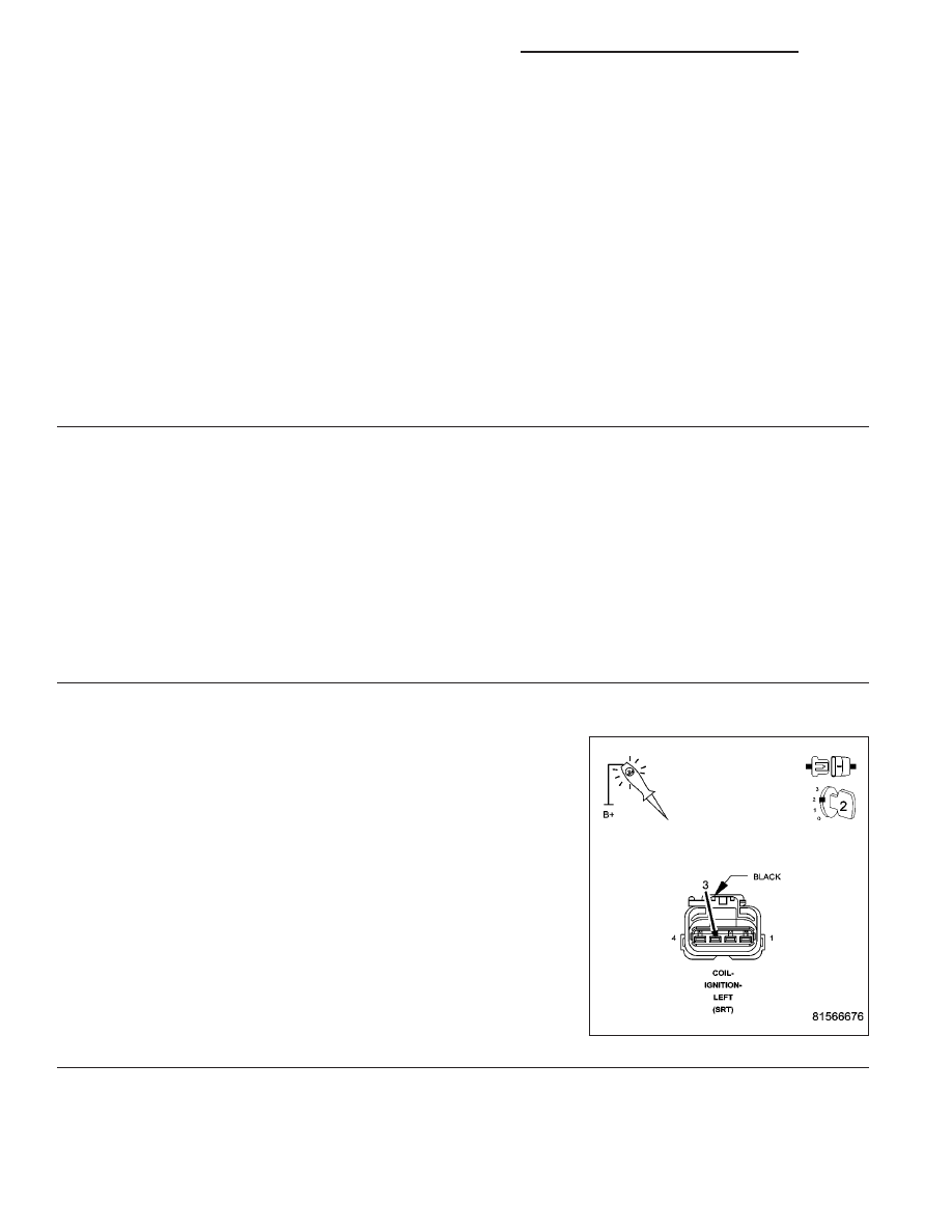
15.
IGNITION COIL
Disconnect the Ignition Coil harness connector.
Remove the Fuel Pump Relay.
Using a 12-volt test light connected to 12-volts, probe the (K133) Coil
Control circuit.
Crank the engine for 5 seconds while observing the test light.
NOTE: The primary resistance of the 8.3L Ignition coil is 0.53 to
0.65 of an ohm at 77°F (25°C).
Does the test light brightly blink/flicker?
Yes
>> Replace the Ignition Coil.
Perform the POWERTRAIN VERIFICATION TEST. (Refer
to 9 - ENGINE - STANDARD PROCEDURE)
No
>> Go To 16
9 - 1758
ENGINE - ELECTRICAL DIAGNOSTICS - SRT-10
DR/DH