Content .. 1024 1025 1026 1027 ..
Dodge Ram Truck 1500-2500-3500. Manual - part 1026
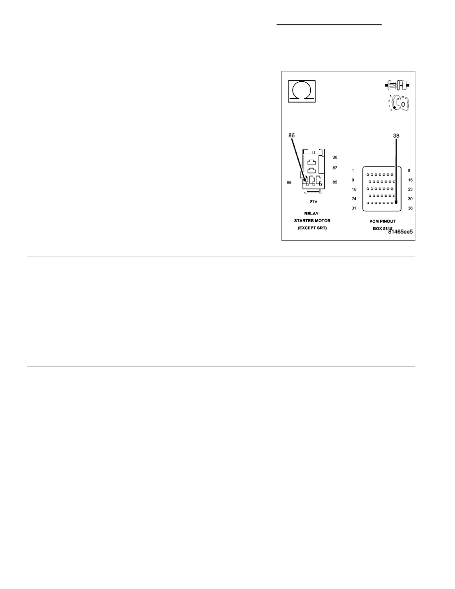
*NO CRANK CONDITION (CONTINUED)
6.
(T752) STARTER RELAY CONTROL CIRCUIT OPEN
Turn the ignition off.
Remove the Starter Relay from the IPM.
Disconnect the C3 PCM harness connector.
Measure the resistance in the (T752) Starter Relay Control circuit from
the Relay terminal to the appropriate terminals of special tool #8815.
Is the resistance below 5.0 ohms?
Yes
>> Replace the Starter Motor Relay.
Perform the POWERTRAIN VERIFICATION TEST. (Refer
to 9 - ENGINE - STANDARD PROCEDURE)
No
>> Repair the open in the (T752) Starter Relay Control circuit.
Perform the POWERTRAIN VERIFICATION TEST. (Refer
to 9 - ENGINE - STANDARD PROCEDURE)
7.
INTERNAL FUSED B+ CIRCUIT OPEN
Turn the ignition off.
Using a 12-volt test light connected to ground, probe the Internal Fused B+ circuit at the Starter Relay terminal.
Does the test light illuminate brightly?
Yes
>> Go To 8
No
>> Repair the excessive resistance in the Internal Fused B+ circuit. Inspect related fuses and repair as
necessary.
Perform the POWERTRAIN VERIFICATION TEST. (Refer to 9 - ENGINE - STANDARD PROCEDURE)
9 - 1026
ENGINE - ELECTRICAL DIAGNOSTICS - 3.7L/4.7L/5.7L
DR/DH