Dodge Ram Truck 1500-2500-3500. Manual - part 79
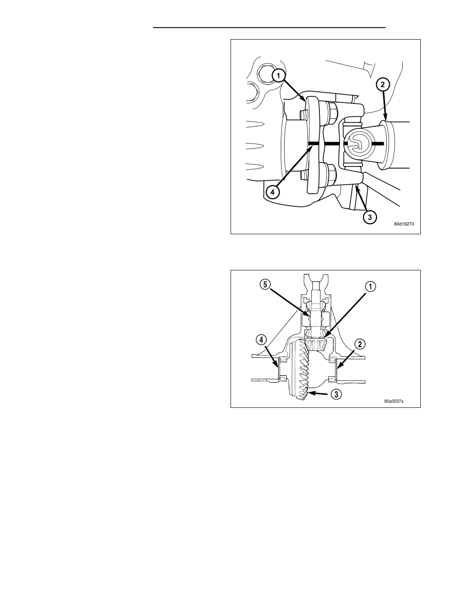
4. Install front propeller shaft (2) with reference marks
(4) aligned and tighten bolts to 115 N·m (85 ft.
lbs.).
5. Install exhaust crossover.
6. Install axle half shafts.
ADJUSTMENTS
Ring gear (3) and pinion are supplied as a matched
sets. Identifying numbers for the ring gear and pinion
are painted onto the pinion gear shaft and the side of
the ring gear. A plus (+) number, minus (–) number or
zero (0) along with the gear set sequence number (01
to 99) is on each gear. This first number is the amount
(in thousandths of an inch) the depth varies from the
standard depth setting of a pinion marked with a (0).
The next two numbers are the sequence number of
the gear set. The standard depth provides the best
teeth contact pattern. Compensation for pinion depth
variance is achieved with select shims (1) located
between the rear pinion bearing cone and pinion gear
head.
If installing a new gear, note the depth variance num-
ber of the original and replacement pinion. Add or sub-
tract this number from the original depth shim/oil slinger to compensate for the difference in the depth variances.
The numbers represent thousands of an inch deviation from the standard. If the number is negative, add that value
to the required thickness of the depth shims. If the number is positive, subtract that value from the thickness of the
depth shim.
3 - 148
FRONT AXLE - C205F
DR/DH