Dodge Ram Truck 1500-2500-3500. Manual - part 69


  Index      Dodge     Dodge Ram Truck 1500-2500-3500 - service repair manual 2005 year


Search            


Content   ..  67  68  69  70   ..


Dodge Ram Truck 1500-2500-3500. Manual - part 69


INSTALLATION

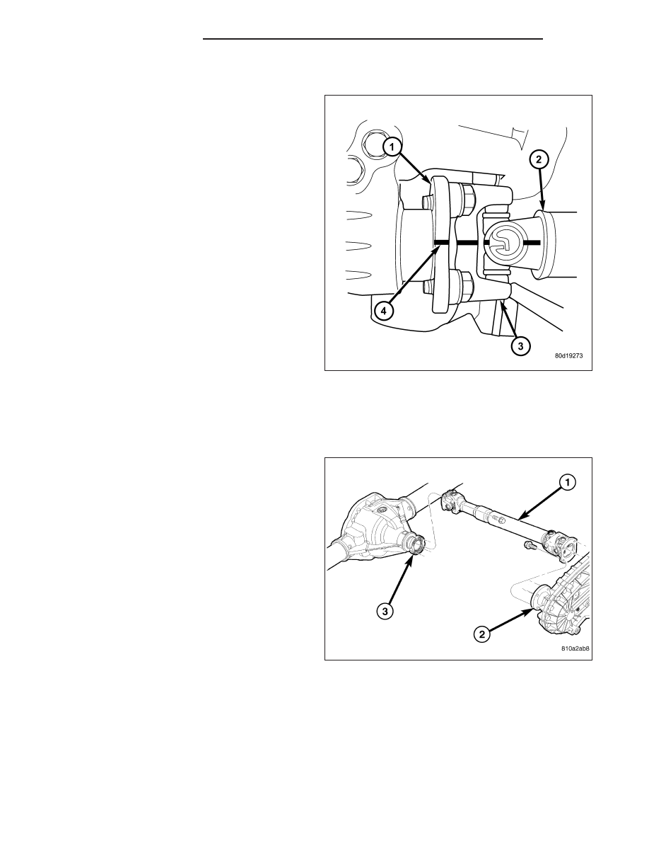
1. Install propeller shaft with all reference marks (4)

aligned.

2. Install with dust boot clamp at transfer case end.

3. Install new axle companion flange bolts and tighten

to 115 N·m (85 ft. lbs.).

NOTE: Companion flange bolts incorporate a Loc-
tite

T

patch, new bolts should be used. If bolts are

not available, clean bolts and apply Loctite

T

242 to

the threads.

4. Install skid plate, if equipped.

SHAFT-PROPELLER HD FRONT

REMOVAL

1. With vehicle in neutral, position vehicle on hoist.

2. Remove exhaust crossover pipe.

3. Mark a line across axle (3)/transfer case (2) com-

panion flange and propeller shaft flange yokes for
installation reference.

4. Remove axle/transfer case companion flange bolts.

5. Remove propeller shaft.

3 - 108

PROPELLER SHAFT

DR/DH

INSTALLATION

1. Install propeller shaft (1) with all reference marks

aligned.

2. Install transfer case companion flange (2) bolts and

tighten to 88 N·m (65 ft. lbs.).

3. Install new axle companion flange (3) bolts and

tighten to 28 N·m (21 ft. lbs.).

NOTE: Companion flange bolts incorporate a Loc-
tite

T

patch, new bolts should be used. If bolts are

not available, clean bolts and apply Loctite

T

242 to

the threads.

4. Install skid plate, if equipped.

SHAFT-PROPELLER REAR

REMOVAL

1. With vehicle in neutral, position vehicle on hoist.

2. Mark pinion flange (3) or yoke and propeller shaft

(1) flange (4) or yoke for installation reference.

DR/DH

PROPELLER SHAFT

3 - 109

3. Mark the outline of the center bearing (1) on the

crossmember for installation reference, if equipped.

4. Remove center bearing mounting nuts (3), if

equipped.

5. Remove pinion flange or yoke clamp bolts.

6. Slide propeller shaft back on transmission then

mark the shaft and transmission for installation ref-
erence.

7. Remove propeller shaft from transmission/ transfer

case.

INSTALLATION

1. Slide slip yoke onto the transmission/transfer case

output shaft with reference marks aligned.

2. Align and install center bearing on crossmember, if

equipped and tighten nuts to 54 N·m (40 ft. lbs.).

3. Align reference marks on propeller shaft (2) and

pinion flange or pinon yoke.

4. Install new companion flange (1) bolts and tighten

to 15 N·m (85 ft. lbs.)

3 - 110

PROPELLER SHAFT

DR/DH

5. Install new SRT-10 yoke clamp (4) bolts and

tighten to 29 N·m (22 ft. lbs.)

NOTE: Companion flange bolts incorporate a Loc-
tite

T

patch, new bolts should be used. If bolts are

not available, clean bolts and apply Loctite

T

242 to

the threads.

BEARING-CENTER

REMOVAL

1. Remove rear propeller shaft.

2. Make installation reference mark (1) on the two

shafts.

3. Remove slip joint boot (4) clamp (3) and separate

the two shafts.

4. Use hammer and punch to tap slinger away from

shaft to provide room for bearing splitter.

5. Position Bearing Splitter Tool 1130 between slinger

and shaft.

CAUTION: Do not damage shaft spline during
removal of center bearing.

6. Set shaft in press and press bearing off the shaft.

INSTALLATION

NOTE: Two types of center bearings are used and
are not interchangeable. Install the same type as
the vehicle was built with.

1. Install new slinger on shaft and drive into position

with appropriate installer tool.

2. Install new center bearing (2) on shaft with Bearing

Installer Tool 6052. Drive on shaft with hammer
until bearing is seated.

3. Clean shaft splines and apply a coat of multi-pur-

pose grease.

DR/DH

PROPELLER SHAFT

3 - 111


Content   ..  67  68  69  70   ..