Dodge Ram. Manual - part 81
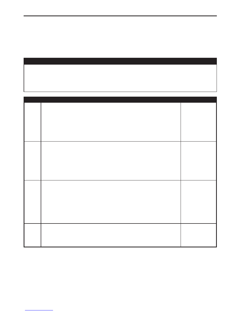
Symptom:
*RIGHT REAR DOOR AJAR CIRCUIT OPEN
POSSIBLE CAUSES
RIGHT REAR DOOR AJAR SWITCH
RIGHT REAR DOOR AJAR SWITCH GROUND CIRCUIT OPEN
RIGHT REAR DOOR AJAR SWITCH SENSE CIRCUIT OPEN
INSTRUMENT CLUSTER - RIGHT REAR DOOR AJAR OPEN
TEST
ACTION
APPLICABILITY
1
Disconnect the Right Rear Door Ajar Switch connector.
Connect a jumper wire between the Sense circuit and the Ground circuit.
With the DRBIII
t in Inputs/Outputs, read the RR DOOR AJAR SW state.
Does the DRBIII
t display CLOSED?
All
Yes
→ Replace the Right Rear Door Ajar Switch.
Perform BODY VERIFICATION TEST - VER 1.
No
→ Go To 2
2
Disconnect the Right Rear Door Ajar switch connector.
Using a 12-volt Test Light connected to 12-volts, probe the Ground circuit.
Does the test light illuminate brightly?
All
Yes
→ Go To 3
No
→ Repair the Right Rear Door Ajar Switch Ground circuit for an
open.
Perform BODY VERIFICATION TEST - VER 1.
3
Disconnect the Right Rear Door Ajar Switch harness connector.
Disconnect the Instrument Cluster C3 harness connector.
Measure the resistance of the Right Rear Door Ajar Switch Sense circuit between the
Instrument Cluster C1 connector and the Door Ajar Switch connector.
Is the resistance below 5.0 ohms?
All
Yes
→ Go To 4
No
→ Repair the Right Rear Door Ajar Switch Sense circuit for an open.
Perform BODY VERIFICATION TEST - VER 1.
4
If there are no possible causes remaining, view repair.
All
Repair
Replace the Instrument Cluster.
Perform BODY VERIFICATION TEST - VER 1.
321
DOOR AJAR