Dodge Neon / Neon SRT-4. Manual - part 436
(2) Position the accumulator into the engine com-
partment.
(3) Install
the
bolt
securing
the
accumulator
mounting bracket. Tighten the bolt to 11 N·m (97 in.
lbs.).
(4) Remove the tape or plugs from the opened suc-
tion and liquid line fittings and accumulator ports.
(5) Lubricate new rubber O-ring seals with clean
refrigerant oil and install them on the suction line
fittings. Use only the specified O-rings as they are
made of a special material for the R-134a system.
Use only refrigerant oil of the type recommended for
the compressor in the vehicle.
(6) Reconnect the suction line fittings to the accu-
mulator.
(7) Install the nuts that secure the suction line fit-
tings to the accumulator. Tighten the nuts to 2.3 N·m
(20 in. lbs.).
(8) Connect the wire harness connector to the A/C
low pressure switch.
(9) If equipped, reinstall the vehicle speed control
servo (Refer to 8 - ELECTRICAL/SPEED CONTROL/
SERVO - INSTALLATION).
(10) Reconnect the negative battery cable.
(11) Evacuate the refrigerant system (Refer to 24 -
HEATING & AIR CONDITIONING - STANDARD
PROCEDURE - REFRIGERANT SYSTEM EVACU-
ATE).
(12) Charge the refrigerant system (Refer to 24 -
HEATING & AIR CONDITIONING - STANDARD
PROCEDURE
-
REFRIGERANT
SYSTEM
CHARGE).
CONDENSATION DRAIN TUBE
DESCRIPTION
Condensation that accumulates in the HVAC hous-
ing is drained out of the housing through a tube and
on to the ground. The condensation drain tube must
be kept open to prevent condensate water from col-
lecting in the bottom of the HVAC housing.
The tapered end of the drain tube is designed to
keep contaminants from entering the HVAC housing.
If the tube is pinched or blocked, condensate cannot
drain, causing water to back up and spill into the
passenger compartment. It is normal to see conden-
sate drainage below the vehicle in warm weather. If
the tube is damaged, it should be replaced.
REMOVAL
(1) Raise vehicle on a hoist.
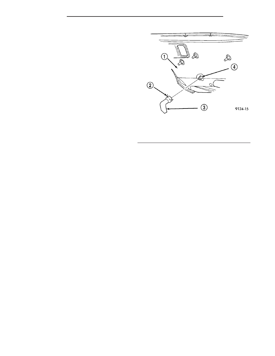
(2) Locate the condensate water drain tube on
right side of dash panel under the hood (Fig. 16).
(3) Squeeze the retaining clamp and remove drain
tube.
INSTALLATION
(1) Position the condensate water drain tube over
the HVAC housing drain.
(2) Squeeze the retaining clamp and install the
condensate water drain tube onto the HVAC housing
drain.
(3) Lower the vehicle.
HEATER CORE
DESCRIPTION
The heater core (Fig. 17) is located in the HVAC
housing, behind the instrument panel. It is a heat
exchanger made of rows of tubes and fins. One end of
the core is fitted with a molded plastic tank that
includes the integral heater core tubes.
OPERATION
Engine coolant is circulated through the heater
hoses and heater core at all times. As the coolant
flows through the heater core, heat removed from the
engine is transferred to the heater core fins and
tubes. Air directed through the heater core picks up
the heat from the heater core fins. The blend door
allows control of the heater output air temperature
by regulating the amount of air that is flowing
through the heater core within the HVAC housing.
The blower motor speed controls the volume of air
flowing through the HVAC housing.
The heater core cannot be repaired and, if faulty or
damaged, it must be replaced.
Fig. 16 Condensate Water Drain Tube – Typical
1 - DASH PANEL
2 - RETAINING CLAMP
3 - CONDENSATE WATER DRAIN TUBE
4 - HVAC HOUSING DRAIN
24 - 52
PLUMBING
PL/SRT-4
ACCUMULATOR - 2.0L LHD MODELS (Continued)