Dodge Neon / Neon SRT-4. Manual - part 426
(9) Remove the screw that secures the clutch coil
pigtail wire connector bracket and ground clip to the
top of the compressor housing.
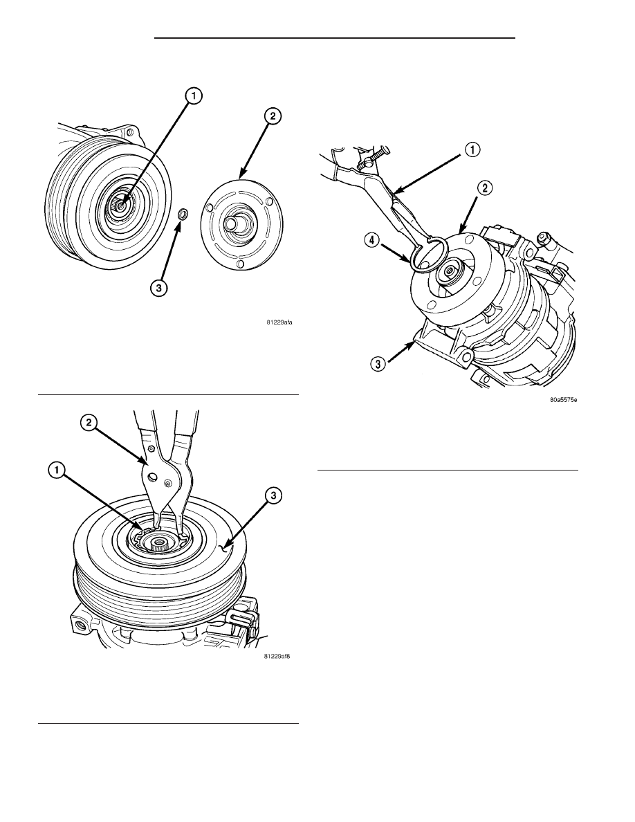
(10) Using snap ring pliers (Special Tool C-4574 or
equivalent), remove the external snap ring that
secures the clutch coil to the front cover of the com-
pressor housing, then slide the clutch coil off of the
compressor (Fig. 6).
INSTALLATION
(1) Align the dowel pin on the back of the clutch
coil with the hole in the compressor front cover and
position the clutch coil onto the compressor. Be cer-
tain that the clutch coil pigtail wires are properly ori-
ented and routed so that they are not pinched
between the compressor front cover and the clutch
coil.
NOTE: A new snap ring must be used to secure the
clutch coil to the compressor. The bevel side of the
snap ring must face outward.
(2) Using snap ring pliers (Special Tool C-4574 or
equivalent), install the external snap ring that
secures the clutch coil to the front cover of the com-
pressor. The bevel side of the snap ring must face
outward and both snap ring eyelets must be oriented
to the right or the left of the clutch coil dowel pin
location on the compressor. Be certain that the snap
ring is fully and properly seated in the groove.
Fig. 4 Clutch Plate and Shim(s)
1 - A/C COMPRESSOR SHAFT
2 - CLUTCH PLATE
3 - SHIM
Fig. 5 Clutch Pulley Snap Ring
1 - SNAP RING
2 - SNAP RING PLIERS
3 - CLUTCH PULLEY AND BEARING
Fig. 6 Clutch Coil Snap Ring
1 - SNAP RING PLIERS
2 - CLUTCH FIELD COIL
3 - A/C COMPRESSOR
4 - SNAP RING
24 - 12
CONTROLS
PL/SRT-4
A/C COMPRESSOR CLUTCH COIL (Continued)