Dodge Neon / Neon SRT-4. Manual - part 381
 

  Index      Dodge     Dodge Neon / Neon SRT-4 - service repair manual 2005 year


Search            


Content   ..  379  380  381  382   ..


Dodge Neon / Neon SRT-4. Manual - part 381


should be stripped of paint and freed from wax and
oil. Scuff surfaces around repair area with 360 grit
wet/dry sandpaper, or equivalent, to assure adhesion
of repair materials.

PATCHING PANELS

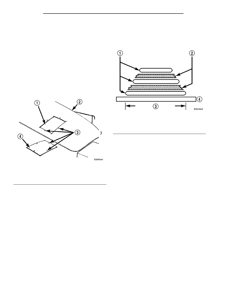
An panel that has extensive puncture type damage

can be repaired by cutting out the damaged material
(Fig. 7). Use a suitable reciprocating saw or cut off
wheel to remove the section of the panel that is dam-
aged. The piece cut out can be used as a template to
shape the new patch. It is not necessary to have
access to the back of the panel to install a patch.
Bevel edges of cutout at 20 degrees to expose a larger
bonding area on the outer side. This will allow for an
increased reinforcement areas.

PANEL PATCH FABRICATIONS

A patch can be fabricated from any rigid fiberglass

panel that has comparable contour with the repair
area. Lift gates and fenders can be used to supply
patch material. If existing material is not available
or compatible, a patch can be constructed with adhe-
sive and reinforcement mesh (dry wall tape). Perform
the following operation if required:

(1) Cover waxed paper or plastic with adhesive

backed nylon mesh (dry wall tape) larger than the
patch required (Fig. 8).

(2) Tape waxed paper or plastic sheet with mesh to

a surface that has a compatible contour to the repair
area.

(3) Apply a liberal coat of adhesive over the rein-

forcement mesh (Fig. 8). If necessary apply a second
or third coat of adhesive and mesh after first coat
has cured. The thickness of the patch should be the
same as the repair area.

(4) After patch has cured, peel waxed paper or

plastic from the back of the patch.

(5) If desired, a thin film coat of adhesive can be

applied to the back of the patch to cover mesh for
added strength.

PANEL PATCH INSTALLATION

(1) Make a paper or cardboard pattern the size

and shape of the cutout hole in the panel.

(2) Trim 3 mm (0.125 in.) from edges of pattern so

patch will have a gap between connecting surfaces.

(3) Using the pattern as a guide, cut the patch to

size.

(4) Cut scrap pieces of patch material into 50 mm

(2 in.) squares to use as patch supports to sustain
the patch in the cutout.

(5) Drill 4 mm (0.160 in.) holes 13 mm (0.5 in.) in

from edge of cutout hole (Fig. 7).

(6) Drill 4 mm (0.160 in.) holes 13 mm (0.5 in.)

away from edge of patch across from holes drilled
around cutout.

(7) Drill 3 mm (0.125 in.) holes in the support

squares 13 mm (0.5 in.) from the edge in the center
of one side.

(8) Scuff the backside of the body panel around the

cutout hole with a scuff pad or sandpaper.

(9) Mix enough adhesive to cover one side of all

support squares.

(10) Apply adhesive to cover one side of all support

squares.

(11) Using number 8 sheet metal screws, secure

support squares to back side of body panel with
adhesive sandwiched between the panel and squares
(Fig. 9).

Fig. 7 DAMAGED PANEL CUTOUT AND PATCH

1 - CUTOUT
2 - DAMAGED BODY PANEL
3 - 4 MM (0.160 IN.) HOLES
4 - PATCH CUT TO SIZE

Fig. 8 FABRICATED PANEL

1 - STRUCTURAL ADHESIVE
2 - FIBERGLASS CLOTH OR FIBERGLASS MESH TAPE
3 - WIDTH OF V-GROOVE
4 - WAXED PAPER

23 - 8

BODY

PL/SRT-4

BODY (Continued)

(12) Position patch in cutout against support

squares and adjust patch until the gap is equal along
all sides (Fig. 10).

(13) Drill 3 mm (0.125 in.) holes in the support

squares through the pre-drilled holes in the patch.

(14) Apply a coat of adhesive to the exposed ends

of the support squares (Fig. 11).

(15) Install screws to hold the patch to support

squares (Fig. 12). Tighten screws until patch surface
is flush with panel surface.

(16) Allow adhesive to cure, and remove all screws.
(17) Using a 125 mm (5 in.) 24 grit disc grinder,

grind a 50 mm (2 in.) to 75 mm (3 in.) wide and 2
mm (0.080 in.) deep path across the gaps around the
patch (Fig. 13). With compressed air, blow dust from
around patch.

(18) Apply adhesive backed nylon mesh (dry wall

tape) over gaps around patch (Fig. 14).

(19) Mix enough adhesive to cover the entire patch

area.

(20) Apply adhesive over the mesh around patch,

and smooth epoxy with a wide spreader to reduce fin-
ish grinding. Use two to three layers of mesh and
adhesive to create a stronger repair (Fig. 15).

Fig. 9 SECURE SUPPORT SQUARES TO BODY

PANEL

1 - SUPPORT SQUARES
2 - SCREWS
3 - DAMAGED BODY PANEL

Fig. 10 POSITION PATCH IN CUTOUT AND ALIGN

1 - CUTOUT
2 - SUPPORT SQUARES

Fig. 11 APPLY ADHESIVE TO SUPPORT SQUARES

1 - APPLICATOR
2 - SUPPORT SQUARES
3 - ADHESIVE

PL/SRT-4

BODY

23 - 9

BODY (Continued)

PATCHED PANEL SURFACING

After patch panel is installed, the patch area can

be finished using the same methods as finishing
other types of body panels. If mesh material is
exposed in the patched area, grind surface down, and
apply a coat of high quality rigid plastic body filler.
Prime, block sand, and paint as required.

Fig. 12 INSTALL SCREWS

1 - PATCH
2 - GAP

Fig. 13 GRIND SURFACE

1 - PATCH
2 - GAP
3 - DISC GRINDER

Fig. 14 COVER GAPS WITH MESH

1 - GROUND DOWN AREA
2 - PATCH
3 - MESH

Fig. 15 COVER MESH WITH ADHESIVE

1 - ADHESIVE
2 - MESH
3 - PATCH
4 - SPREADER

23 - 10

BODY

PL/SRT-4

BODY (Continued)

SPECIFICATIONS

SPECIFICATIONS - TORQUE

TORQUE SPECIFICATIONS

DESCRIPTION

N·m

Ft. Lbs.

In. Lbs.

All seat belt anchor bolts

40

30

All seat belt anchor nuts

40

30

All seat belt retractor bolts

40

30

Decklid latch striker

22

16

Front seat track to floor pan bolts

55

40

Front seat inboard pivot bolt

40

30

Front seat recliner to seat cushion frame

12

9

Front seat track to cushion frame bolt

12

9

Front seat back

40

30

Front seat back recliner to seat back

12

9

Front door hinge to hinge pillar bolt

28

21

Front door hinge to door nuts and bolt

28

21

Front door latch striker

28

20

Hood latch striker

13.5

10

Rear door glass to regulator bolt

11

105

Rear door hinge to B-pillar bolt

28

20

Rear door hinge to door bolt

28

20

Rear door latch striker

28

20

Rear seat back and seat belt buckle anchor nut

57

42

Sunroof module

5

44

BODY LUBRICATION

LUBRICATION REQUIREMENTS

Body

mechanisms

and

linkages

should

be

inspected, cleaned, and lubricated, as required, to
maintain ease of operation and to provide protection
against rust and wear. When performing other under
hood services, the hood latch release mechanism and
safety catch should be inspected, cleaned, and lubri-
cated. During the winter season, external door lock
cylinders should be lubricated to assure proper oper-
ation when exposed to water and ice.

Prior to the application of any lubricant, the parts

concerned should be wiped clean to remove dust and
grit. If necessary, a suitable solvent can be used to
clean the item to be lubricated. After lubricating a
component, any excess oil or grease should be
removed.

LUBRICANT APPLICATION

DOOR LOCK CYLINDERS

(1) Apply a small amount of lubricant directly into

the lock cylinder.

(2) Apply a small amount of lubricant to the key.
(3) Insert key into lock cylinder and cycle the

mechanism from the locked to the unlocked position.

NOTE: Do not add more lubricant.

(4) Cycle the lock cylinder mechanism several

times to allow the lubricant to flow throughout the
cylinder.

(5) Wipe all lubricant from exterior of lock cylinder

and key.

ALL OTHER BODY MECHANISMS

(1) Clean component as described above.
(2) Apply specified lubricant to all pivoting and

sliding contact areas of component.

PL/SRT-4

BODY

23 - 11

BODY (Continued)


Content   ..  379  380  381  382   ..