Dodge Neon / Neon SRT-4. Manual - part 371
 

  Index      Dodge     Dodge Neon / Neon SRT-4 - service repair manual 2005 year


Search            


Content   ..  369  370  371  372   ..


Dodge Neon / Neon SRT-4. Manual - part 371


OPERATION

The relay is supplied fused B+ voltage, energized

by the PCM/TCM, and is used to supply power to the
solenoid pack when the transmission is in normal
operating mode. When the relay is “off”, no power is
supplied to the solenoid pack and the transmission is
in “limp-in” mode. After a controller reset (ignition
key turned to the “run” position or after cranking
engine), the PCM/TCM energizes the relay. Prior to
this, the PCM/TCM verifies that the contacts are
open by checking for no voltage at the switched bat-
tery terminals. After this is verified, the voltage at
the solenoid pack pressure switches is checked. After
the relay is energized, the PCM/TCM monitors the
terminals to verify that the voltage is greater than 3
volts.

TRANSMISSION RANGE
SENSOR

DESCRIPTION

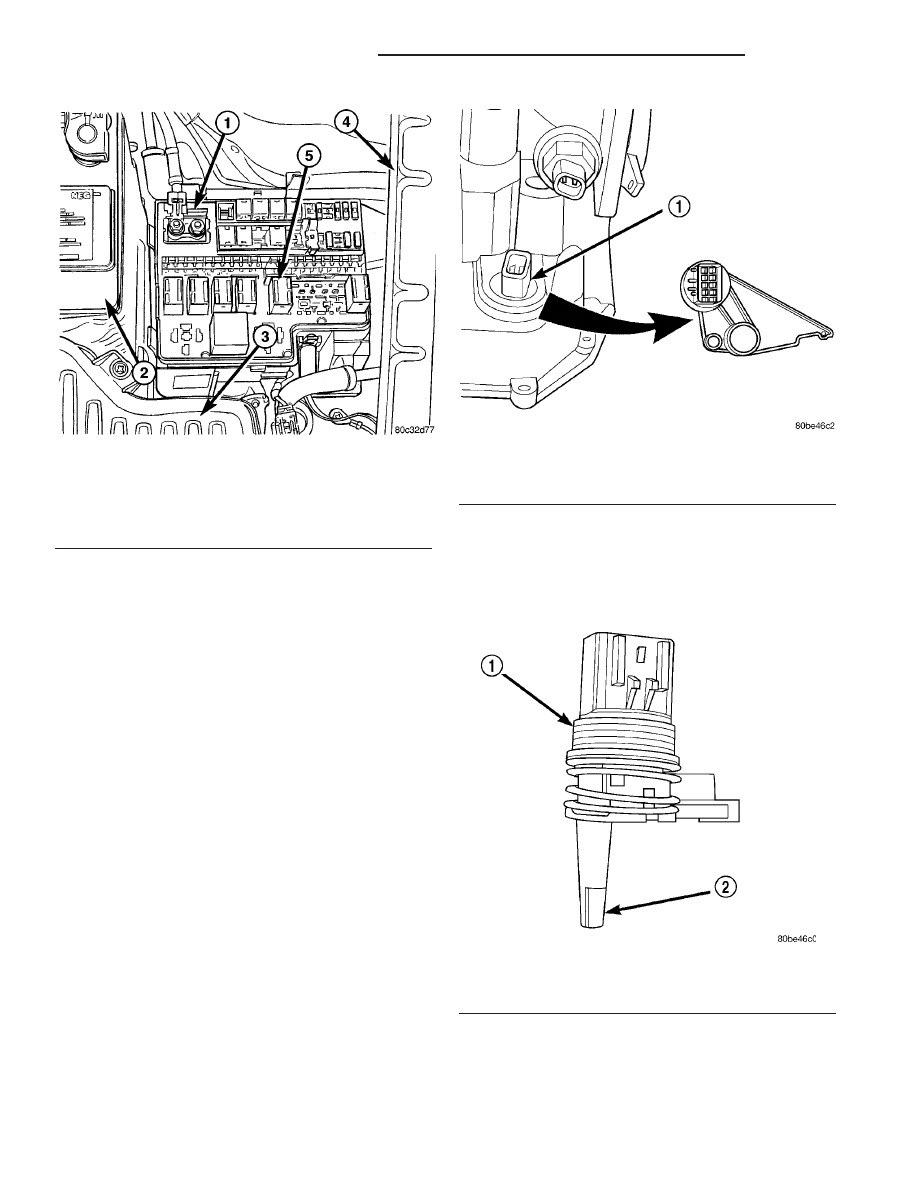
The Transmission Range Sensor (TRS) is mounted

to the top of the valve body inside the transaxle and
can only be serviced by removing the valve body. The
electrical connector extends through the transaxle
case (Fig. 326).

The Transmission Range Sensor (TRS) has four

switch contacts that monitor shift lever position and
send the information to the PCM/TCM.

The TRS also has an integrated temperature sen-

sor (thermistor) that communicates transaxle tem-
perature to the TCM and PCM (Fig. 327).

OPERATION

The Transmission Range Sensor (TRS) (Fig. 326)

communicates shift lever position (SLP) to the PCM/
TCM as a combination of open and closed switches.
Each shift lever position has an assigned combina-

Fig. 325 Transmission Control Relay Location

1 - POWER DISTRIBUTION CENTER (PDC)
2 - BATTERY
3 - AIR CLEANER/THROTTLE BODY ASSY.
4 - LEFT FENDER
5 - TRANSMISSION CONTROL RELAY

Fig. 326 Transmission Range Sensor (TRS)

Location

1 - TRANSMISSION RANGE SENSOR

Fig. 327 Transmission Temperature Sensor

1 - TRANSMISSION RANGE SENSOR
2 - TEMPERATURE SENSOR

21 - 268

40TE AUTOMATIC TRANSAXLE

PL/SRT-4

TRANSMISSION CONTROL RELAY (Continued)

tion of switch states (open/closed) that the PCM/TCM
receives from four sense circuits. The PCM/TCM
interprets

this

information

and

determines

the

appropriate transaxle gear position and shift sched-
ule.

Since there are four switches, there are 16 possible

combinations of open and closed switches (codes).
Seven of these codes are related to gear position and
three are recognized as “between gear” codes. This
results in six codes which should never occur. These
are called “invalid” codes. An invalid code will result
in a DTC, and the PCM/TCM will then determine the
shift lever position based on pressure switch data.
This allows reasonably normal transmission opera-
tion with a TRS failure.

TRS SWITCH STATES

SLP

T42

T41

T3

T1

P

CL

CL

CL

OP

R

CL

OP

OP

OP

N

CL

CL

OP

CL

OD

OP

OP

OP

CL

3

OP

OP

CL

OP

L

CL

OP

CL

CL

TRANSMISSION TEMPERATURE SENSOR

The TRS has an integrated thermistor (Fig. 327)

that the PCM/TCM uses to monitor the transmis-
sion’s sump temperature. Since fluid temperature
can affect transmission shift quality and convertor
lock up, the PCM/TCM requires this information to
determine which shift schedule to operate in. The
PCM also monitors this temperature data so it can
energize the vehicle cooling fan(s) when a transmis-
sion “overheat” condition exists. If the thermistor cir-
cuit fails, the PCM/TCM will revert to calculated oil
temperature usage.

CALCULATED TEMPERATURE

A failure in the temperature sensor or circuit will

result in calculated temperature being substituted for
actual temperature. Calculated temperature is a pre-
dicted fluid temperature which is calculated from a
combination of inputs:

• Battery (ambient) temperature

• Engine coolant temperature

• In-gear run time since start-up

REMOVAL

(1) Remove valve body assembly from transaxle.

(Refer to 21 - TRANSMISSION/TRANSAXLE/AUTO-
MATIC - 41TE/VALVE BODY - REMOVAL)

(2) Remove transmission range sensor retaining

screw and remove sensor from valve body (Fig. 328).

(3) Remove TRS from manual shaft.

INSTALLATION

(1) Install transmission range sensor (TRS) to the

valve body and torque retaining screw (Fig. 328) to 5
N·m (45 in. lbs.).

(2) Install valve body to transaxle. (Refer to 21 -

TRANSMISSION/TRANSAXLE/AUTOMATIC

-

41TE/VALVE BODY - INSTALLATION)

VALVE BODY

DESCRIPTION

The valve body assembly consists of a cast alumi-

num valve body, a separator plate, and transfer
plate. The valve body contains valves and check balls
that control fluid delivery to the torque converter
clutch, solenoid/pressure switch assembly, and fric-
tional clutches. The valve body contains the following
components (Fig. 329):

• Regulator valve

• Solenoid switch valve

• Manual valve

• Converter clutch switch valve

• Converter clutch control valve

• Torque converter regulator valve

• Low/Reverse switch valve
In addition, the valve body also contains the ther-

mal valve, #2,3&4 check balls, the #5 (overdrive)
check valve and the 2/4 accumulator assembly. (Refer
to 21 - TRANSMISSION/TRANSAXLE/AUTOMATIC
- 41TE/VALVE BODY - DISASSEMBLY)

Fig. 328 Remove Transmission Range Sensor

1 - TRANSMISSION RANGE SENSOR
2 - MANUAL VALVE CONTROL PIN
3 - RETAINING SCREW

PL/SRT-4

40TE AUTOMATIC TRANSAXLE

21 - 269

TRANSMISSION RANGE SENSOR (Continued)

OPERATION

NOTE: Refer to the Hydraulic Schematics for a
visual aid in determining valve location, operation
and design.

REGULATOR VALVE

The regulator valve controls hydraulic pressure in

the transaxle. It receives unregulated pressure from
the pump, which works against spring tension to
maintain oil at specific pressures. A system of sleeves
and ports allows the regulator valve to work at one of
three predetermined pressure levels. Regulated oil
pressure is also referred to as “line pressure.”

SOLENOID SWITCH VALVE

The solenoid switch valve controls line pressure

from the LR/CC solenoid. In one position, it allows
the low/reverse clutch to be pressurized. In the other,
it directs line pressure to the converter control and
converter clutch valves.

MANUAL VALVE

The manual valve is operated by the mechanical

shift linkage. Its primary responsibility is to send
line pressure to the appropriate hydraulic circuits
and solenoids. The valve has three operating ranges
or positions.

CONVERTER CLUTCH SWITCH VALVE

The main responsibility of the converter clutch

switch valve is to control hydraulic pressure applied
to the front (off) side of the converter clutch piston.
Line pressure from the regulator valve is fed to the
torque converter regulator valve, where it passes
through the valve, and is slightly regulated. The
pressure is then directed to the converter clutch
switch valve and to the front side of the converter
clutch piston. This pressure pushes the piston back
and disengages the converter clutch.

CONVERTER CLUTCH CONTROL VALVE

The converter clutch control valve controls the

back (on) side of the torque converter clutch. When
the PCM/TCM energizes or modulates the LR/CC
solenoid to apply the converter clutch piston, both
the converter clutch control valve and the converter

Fig. 329 Valve Body Assembly

1 - VALVE BODY

5 - MANUAL VALVE

2 - T/C REGULATOR VALVE

6 - CONVERTER CLUTCH SWITCH VALVE

3 - L/R SWITCH VALVE

7 - SOLENOID SWITCH VALVE

4 - CONVERTER CLUTCH CONTROL VALVE

8 - REGULATOR VALVE

21 - 270

40TE AUTOMATIC TRANSAXLE

PL/SRT-4

VALVE BODY (Continued)

control valve move, allowing pressure to be applied to
the back side of the clutch.

T/C REGULATOR VALVE

The torque converter regulator valve slightly regu-

lates the flow of fluid to the torque converter.

LOW/REVERSE SWITCH VALVE

The low/reverse clutch is applied from different

sources, depending on whether low (1st) gear or
reverse is selected. The low/reverse switch valve
alternates positions depending on from which direc-
tion fluid pressure is applied. By design, when the
valve is shifted by fluid pressure from one channel,
the opposing channel is blocked. The switch valve
alienates the possibility of a sticking ball check, thus
providing consistent application of the low/reverse
clutch under all operating conditions.

REMOVAL

NOTE: If valve body is replaced or reconditioned,
the TCM Quick Learn Procedure must be per-
formed. (Refer to 8 - ELECTRICAL/ELECTRONIC
CONTROL

MODULES/TRANSMISSION

CONTROL

MODULE - STANDARD PROCEDURE)

(1) Disconnect battery negative cable.
(2) Remove air cleaner/throttle body assembly.
(3) Disconnect gearshift cable from manual valve

lever.

(4) Remove manual valve lever from manual shaft.
(5) Disconnect transmission range sensor (TRS).
(6) Raise vehicle on hoist.
(7) Remove oil pan bolts (Fig. 330).

(8) Remove oil pan (Fig. 331).

(9) Remove oil filter (Fig. 332).

(10) Remove the valve body-to-transaxle case bolts

(Fig. 333).

Fig. 330 Oil Pan Bolts

1 - OIL PAN BOLTS (USE RTV UNDER BOLT HEADS)

Fig. 331 Oil Pan

1 - OIL PAN
2 - 1/8 INCH BEAD OF RTV SEALANT
3 - OIL FILTER

Fig. 332 Oil Filter

1 - OIL FILTER
2 - O-RING

PL/SRT-4

40TE AUTOMATIC TRANSAXLE

21 - 271

VALVE BODY (Continued)


Content   ..  369  370  371  372   ..