Dodge Neon / Neon SRT-4. Manual - part 328


  Index      Dodge     Dodge Neon / Neon SRT-4 - service repair manual 2005 year


Search            


Content   ..  326  327  328  329   ..


Dodge Neon / Neon SRT-4. Manual - part 328


INSPECTION

Wash all components in a suitable solvent and

blow-dry with compressed air (except bearings).
Inspect all components for excessive wear. Minor
irregular wear and small gear chips are acceptable
and do not inhibit differential operation. However,
large gear chips or components discolored due to lack
of lubrication should result in differential replace-
ment.

ASSEMBLY

NOTE: The Quaife ATB Differential is serviced only
as a complete assembly. The only serviceable com-
ponents are the ring gear and tapered roller bear-
ings. No other component replacement will be
possible.

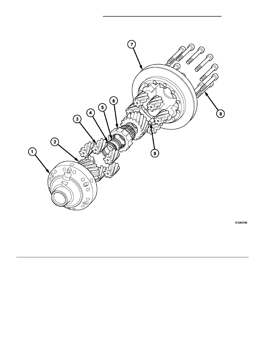
(1) Assemble and install differential components

as shown in (Fig. 104). Make sure center pack
(spring housing and belleville spring washers)
is assembled as shown in 
(Fig. 105).

Fig. 104 Differential Components

1 - GEAR BODY (SMALL SIDE)

6 - CENTER BLOCK

2 - SUN GEAR (2)

7 - GEAR BODY (FLANGE SIDE)

3 - PLANET PINION (12)

8 - BOLT (11)

4 - SPRING HOUSING (2)

9 - DOWEL

5 - BELLEVILLE WASHER (6)

21 - 96

T850 MANUAL TRANSAXLE

PL/SRT-4

DIFFERENTIAL (Continued)

(2) Noting

position

of

locating

dowel,

install

flanged gear body halve.

(3) Apply Mopar

t Lock & Seal Adhesive to the

eleven (11) gear body halve bolts. Install and torque
to 39 N·m (28 ft. lbs.).

(4) Install ring gear. Install and torque twelve (12)

bolts to 95 N·m (70 ft. lbs.) (Fig. 106).

(5) Using Tool 8473 and Tool 8491, install differen-

tial side bearings with arbor press (Fig. 107).

ADJUSTMENTS

ADJUSTMENT - DIFFERENTIAL TURNING
TORQUE

NOTE: Differential turning torque should only be
measured with the geartrain out of the transaxle. If
measurement is taken with transaxle assembled, an
inaccurate measurement will result.

NOTE: All differential cover-to-case bolts and exten-
sion housing-to-case bolts must be installed and
torqued to obtain accurate measurement.

(1) If transaxle is assembled, remove geartrain

and leave differential in place. (Refer to 21 - TRANS-
MISSION/TRANSAXLE/MANUAL - DISASSEMBLY)

Fig. 105 Quaife ATB Differential

1 - GEAR BODY (FLANGED SIDE)
2 - BOLT (11)
3 - SUN GEAR (2)
4 - PLANET PINION (12)
5 - CENTER PACK
6 - GEAR BODY (SMALL SIDE)

Fig. 106 Ring Gear-to-Case Bolts

1 - BOLT (12)

Fig. 107 Differential Bearing Installation

1 - TOOL C-4171
2 - TOOL 8473
3 - BEARING
4 - TOOL 8491

PL/SRT-4

T850 MANUAL TRANSAXLE

21 - 97

DIFFERENTIAL (Continued)

(2) Install differential cover and torque differential

cover-to-case bolts to 54 N·m (40 ft. lbs.).

(3) Install extension housing and torque extension

housing-to-case bolts to 28 N·m (250 in. lbs.).

(4) Place transaxle on work bench so axle center-

line is parallel to the ground.

(5) Install turning torque tool C-4995 to differen-

tial at side opposite extension housing.

(6) Using an in. lb./N·m dial indicator, rotate dif-

ferential case multiple times and record measure-
ment (Fig. 108). Differential turning torque should be
within 2.3-3.4 N·m (20-30 in. lbs.). Refer to shim
chart for proper shim selection. If turning torque
measured is less than 2.3 N·m (20 in. lbs.), install a
thicker shim. If turning torque measured is greater
than 3.4 N·m (30 in. lbs.), install a thinner shim.

DIFFERENTIAL BEARING SHIM CHART

PART NUMBER

SHIM THICKNESS

METRIC (MM)

STANDARD (STD)

4659242

0.50

0.0197

4659243

0.54

0.0213

4659247

0.58

0.0228

4659248

0.62

0.0244

4659249

0.66

0.0260

4659250

0.70

0.0276

4659251

0.74

0.0291

4659252

0.78

0.0307

4659253

0.82

0.0322

4659254

0.86

0.0339

4659255

0.90

0.0354

4659256

0.94

0.0370

4659257

0.98

0.0386

4659258

1.02

0.0402

4659259

1.06

0.0418

4659260

1.10

0.0434

4659261

1.14

0.0449

4659262

1.18

0.0465

4659263

1.22

0.0481

Fig. 108 Differential Turning Torque Measurement

1 - DIAL TORQUE WRENCH
2 - TOOL C-4995

21 - 98

T850 MANUAL TRANSAXLE

PL/SRT-4

DIFFERENTIAL (Continued)

PART NUMBER

SHIM THICKNESS

METRIC (MM)

STANDARD (STD)

4659264

1.26

0.0497

4659265

1.30

0.0512

4659266

1.34

0.0528

4659267

1.38

0.0544

4659268

1.42

0.0560

4659269

1.46

0.0575

4659270

1.50

0.0591

4659271

1.54

0.0607

4659272

1.58

0.0623

4659273

1.62

0.0638

4659274

1.66

0.0654

4659275

1.70

0.0670

4659276

1.74

0.0690

4659277

1.78

0.0701

4659278

1.82

0.0716

4659279

1.86

0.0732

4659280

1.90

0.0748

4659281

1.94

0.0763

4659282

1.98

0.0779

4659283

2.02

0.0795

4659284

2.06

0.0811

FLUID

STANDARD PROCEDURE

STANDARD PROCEDURE - FLUID LEVEL
CHECK

NOTE: For proper fluid level check intervals, (Refer
to LUBRICATION & MAINTENANCE/MAINTENANCE
SCHEDULES - DESCRIPTION)

The fluid required in this transaxle is Mopar

t

ATF+4 along with 0.12L (4 oz.) Mopar Limited Slip
Additive/Friction Modifier (P/N 04318060AB).. Use of
substitute fluids may result in improper transaxle
operation and/or failure.

(1) Raise vehicle on hoist.
(2) Remove transaxle fill plug (Fig. 109).
(3) Inspect fluid level. Fluid should be within 3/16”

below fill hole. Add Mopar

t ATF+4 as neccessary.

(4) Install fill plug, ensuring it is properly seated.
(5) Lower vehicle.

Fig. 109 Transaxle Fill Plug

1 - FILL PLUG
2 - END COVER

PL/SRT-4

T850 MANUAL TRANSAXLE

21 - 99

DIFFERENTIAL (Continued)


Content   ..  326  327  328  329   ..