Dodge Neon / Neon SRT-4. Manual - part 299
OPERATION - POWER STEERING GEAR
Turning of the steering wheel is converted into lat-
eral (side-to side) travel through the meshing of the
helical pinion teeth with the rack teeth located in the
steering gear. This lateral travel pushes and pulls
the tie rods to change the direction of the vehicle’s
front wheels.
Power assist is provided by a pump and is con-
trolled by an open-center, rotary type control valve. It
directs fluid to either side of the gear’s integral steer-
ing rack piston. Depending on the rotation of the
steering wheel, more fluid pressure is directed to one
side of the rack piston compared to the other.
Road feel is controlled by the diameter of a torsion
bar which initially steers the vehicle. As steering
effort increases, as in a turn, the torsion bar twists
causing relative rotary motion between the rotary
valve body and valve spool. This movement restricts
fluid flow to one side of the integral rack piston and
redirects fluid behind the other side of the integral
rack piston, building up hydraulic pressure, thus
assisting in the turning effort.
REMOVAL
REMOVAL - POWER STEERING GEAR
NOTE: Before proceeding with this procedure,
(Refer to 19 - STEERING - WARNING).
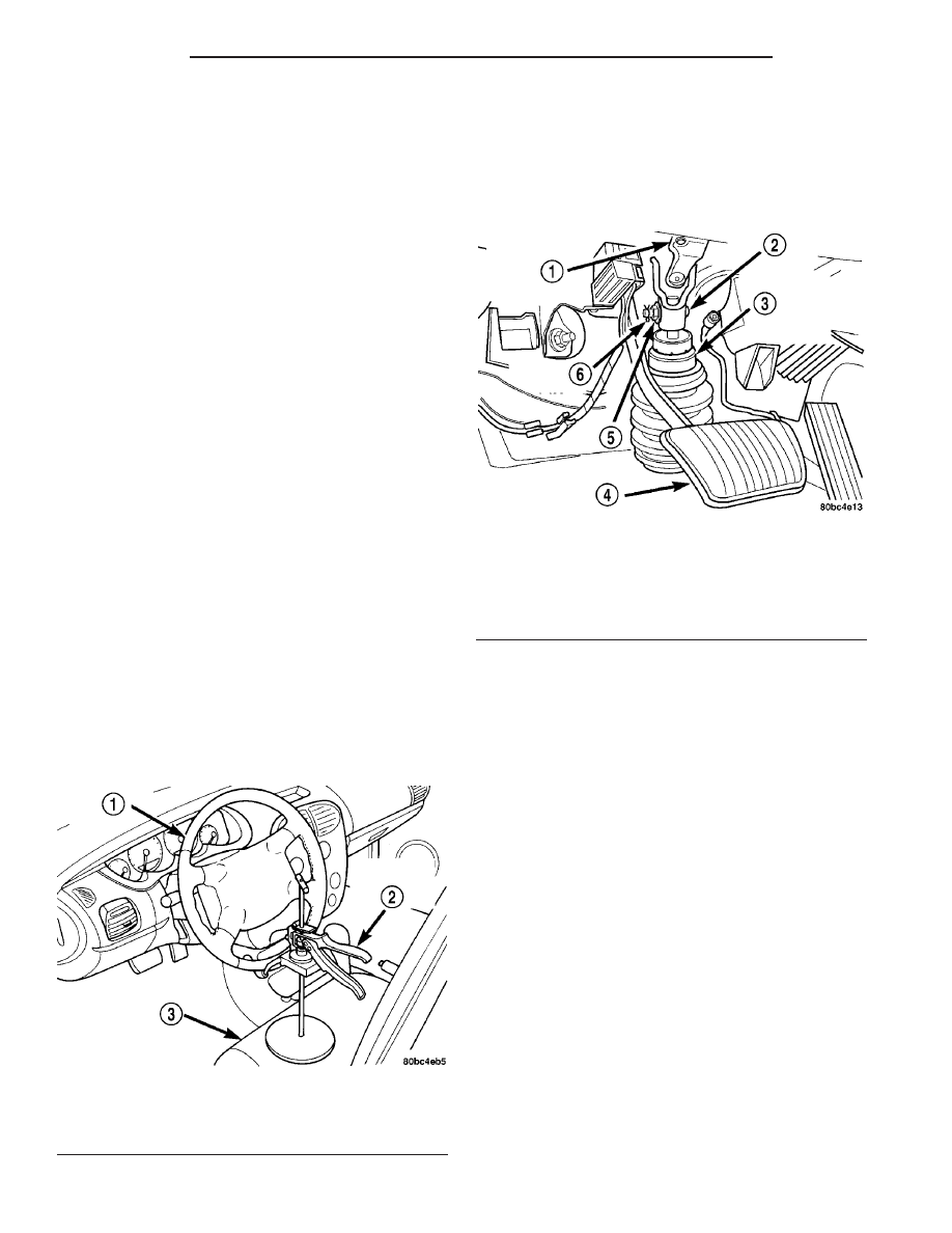
(1) Place the steering wheel in the STRAIGHT-
AHEAD position. Using a steering wheel holder, lock
the steering wheel in place to keep it from rotating
(Fig. 2). This keeps the clockspring in the proper ori-
entation.
(2) Inside the passenger compartment, remove the
steering column coupling retainer pin, back off the
pinch bolt nut, and remove the steering column cou-
pling pinch bolt (Fig. 3) (the pinch bolt nut is caged
to the coupling and is not removable). Separate the
upper and lower steering column couplings.
(3) Raise the vehicle. (Refer to LUBRICATION &
MAINTENANCE/HOISTING - STANDARD PROCE-
DURE).
(4) Remove both front tire and wheel assemblies
from the vehicle (Refer to 22 - TIRES/WHEELS -
REMOVAL).
(5) Remove nuts attaching both outer tie rods to
the steering knuckles (Fig. 4). Remove each nut by
holding the tie rod stud stationary while loosening
and removing the nut with a wrench.
(6) Remove the outer tie rod from the steering
knuckles using Remover, Special Tool MB991113
(Fig. 5).
(7) Remove the tie rod heat shield.
(8) Release the locking tab on the wiring harness
connector for the power steering fluid pressure
switch before connector removal. Remove the wiring
harness connector from the power steering fluid pres-
sure switch (Fig. 6).
(9) Back out the tube nut securing the power
steering fluid pressure hose to the gear.
(10) Loosen the clamp, then disconnect the fluid
cooler hose from the gear.
(11) Open the routing clips on the front of the
power steering gear and remove the power steering
fluid pressure hose from the routing clips. At the
Fig. 2 Steering Wheel Holder (Typical)
1 - STEERING WHEEL
2 - STEERING WHEEL HOLDER
3 - DRIVERS SEAT
Fig. 3 Steering Column Couplings
1 - STEERING COLUMN UPPER COUPLING
2 - PINCH BOLT
3 - STEERING COLUMN LOWER COUPLING
4 - BRAKE PEDAL
5 - NUT
6 - RETAINER PIN
19 - 28
GEAR
PL/SRT-4
GEAR (Continued)