Dodge Neon / Neon SRT-4. Manual - part 281
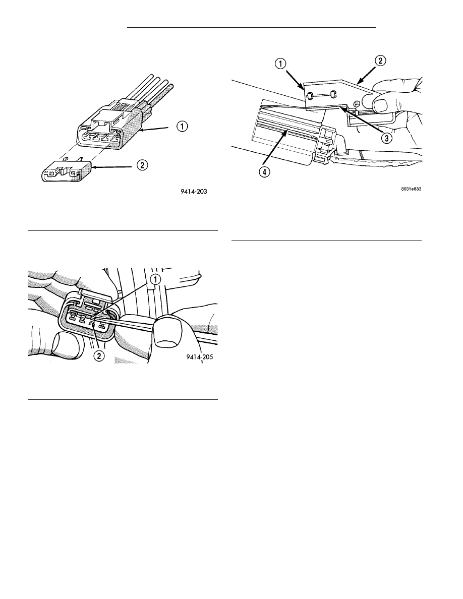
(2) Pull off blue locking wedge (Fig. 5).
(3) Using a small screwdriver lift locking finger
away from terminal and push terminal out of connec-
tor (Fig. 6).
(4) Push level sensor signal and ground terminals
out of the connector (Fig. 6).
(5) Slide level sensor wires through opening fuel
pump module (Fig. 7).
(6) Slide level sensor out of installation channel in
module.
INSTALLATION
(1) Insert level sensor wires into bottom of opening
in module.
(2) Wrap wires into groove in back of level sensor.
(3) While feeding wires into guide grooves, slide
level sensor up into channel until it snaps into place
(Fig. 7). Ensure tab at bottom of sensor locks in
place.
(4) Install level sensor wires in connector. Push
the wires up through the connector and then pull
them down until they lock in place. Ensure signal
and ground wires are installed in the correct posi-
tion.
(5) Install locking wedge on connector.
(6) Push connector up into bottom of fuel pump
module electrical connector.
(7) Install fuel pump module. Refer to Fuel Pump
Module in this section.
FUEL LINES
DESCRIPTION - FUEL LINES/HOSES AND
CLAMPS
Also refer to Quick-Connect Fittings.
WARNING: THE FUEL SYSTEM IS UNDER A CON-
STANT PRESSURE (EVEN WITH THE ENGINE OFF).
BEFORE SERVICING ANY FUEL SYSTEM HOSES,
FITTINGS OR LINES, THE FUEL SYSTEM PRES-
SURE MUST BE RELEASED. REFER TO THE FUEL
SYSTEM PRESSURE RELEASE PROCEDURE IN
THIS GROUP. THIS MAY RESULT IN PERSONAL
INJURY OR DEATH.
The lines/tubes/hoses used on fuel injected vehicles
are of a special construction. This is due to the
higher fuel pressures and the possibility of contami-
nated fuel in this system. If it is necessary to replace
these lines/tubes/hoses, use new original equipment
lines/tubes/hoses.
If equipped: The hose clamps used to secure rub-
ber hoses on vehicles are of a special rolled edge con-
struction. This construction is used to prevent the
edge of the clamp from cutting into the hose. Only
these rolled edge type clamps may be used in this
Fig. 5 Wire Terminal Locking Wedge
1 - ELECTRICAL CONNECTOR
2 - BLUE LOCKING WEDGE
Fig. 6 Removing Wires From Connector
1 - LOCKING FINGER
2 - WIRE TERMINAL
Fig. 7 Level Sensor
1 - REAR VIEW OF LEVEL SENSOR
2 - LEVEL SENSOR
3 - WRAP WIRES IN GROOVE
4 - CHANNEL FOR LEVEL SENSOR
14 - 6
FUEL DELIVERY
PL/SRT-4
FUEL LEVEL SENDING UNIT / SENSOR (Continued)