Dodge Neon / Neon SRT-4. Manual - part 278


  Index      Dodge     Dodge Neon / Neon SRT-4 - service repair manual 2005 year


Search            


Content   ..  276  277  278  279   ..


Dodge Neon / Neon SRT-4. Manual - part 278


Fig. 11 FORWARD FRAME AND CROSSMEMBER

13 - 10

FRAME & BUMPERS

PL/SRT-4

FRAME (Continued)
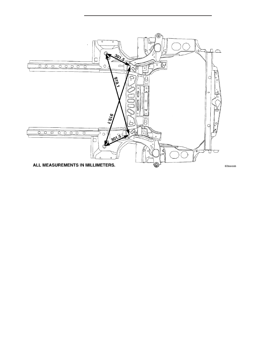
Fig. 12 REAR FRAME SECTION SIDE AND BOTTOM VIEW

PL/SRT-4

FRAME & BUMPERS

13 - 11

FRAME (Continued)

FRONT CROSSMEMBER

DESCRIPTION

The front suspension crossmember must be prop-

erly installed to achieve design camber, caster set-
tings and wheel stagger. The crossmember can be
installed out of position on the frame rails due to its
design. Bolts and cage nuts hold the rear of the
crossmember to the frame torque boxes. Bolts and
J-nuts hold the front of the crossmember to the
frame rails. No designed in locating device is used to
position the crossmember in the vehicle. Before
removing the crossmember mark the frame torque
box around the rear mounting location to aid instal-
lation. A crossmember that is removed during service
must be installed in the same position from which it
was removed. To verify that crossmember is in the
proper position, refer to the dimensions provided.
Front end dimensions are gauged from the principal
locating point (PLP) holes located under the frame
torque boxes rearward of the front wheels. After
removal and installation of the crossmember is per-
formed, verify that front suspension alignment is
within specifications. If camber, caster settings and
thrust angle are not within specifications, loosen and
reposition crossmember to bring suspension within
specifications. For additional information, (Refer to 2
-

SUSPENSION/WHEEL ALIGNMENT

-

STAN-

DARD PROCEDURE).

REMOVAL

FRONT SUSPENSION CROSSMEMBER

CAUTION: If the front suspension crossmember is
being replaced due to collision damage, inspect the
steering column lower coupling for damage. Refer
to COLUMN in STEERING.

REMOVAL

(1) Raise the vehicle. (Refer to LUBRICATION &

MAINTENANCE/HOISTING - STANDARD PROCE-
DURE)

(2) Remove both front tire and wheel assemblies

from the vehicle.

(3) Remove both stabilizer bar links from the vehi-

cle (Fig. 13). Remove each link by holding the upper
retainer/nut with a wrench and turning the link bolt.

(4) Remove the stabilizer bar cushion retainer

bolts and retainers (Fig. 13), and remove the stabi-
lizer bar with cushions attached from the vehicle.

(5) Remove the nut and pinch bolt clamping each

ball joint stud to the steering knuckle (Fig. 14).

CAUTION: After removing the steering knuckle from
the ball joint stud, do not pull outward on the
knuckle. Pulling the steering knuckle outward at
this point can separate the inner C/V joint on the
driveshaft. Refer to FRONT DRIVESHAFTS in the
DIFFERENTIAL AND DRIVELINE group for further
information.

NOTE: Use caution when separating the ball joint
stud from the steering knuckle, so the ball joint seal
does not get cut.

Fig. 13 Stabilizer Bar

1 - STABILIZER BAR CUSHION RETAINERS
2 - CUSHIONS
3 - FRONT STABILIZER BAR
4 - STABILIZER BAR LINKS

Fig. 14 Ball Joint Bolt And Nut

1 - NUT
2 - BOLT
3 - BALL JOINT

13 - 12

FRAME & BUMPERS

PL/SRT-4

(6) Separate each ball joint stud from the steering

knuckle by prying down on lower control arm and up
against the ball joint boss on the steering knuckle
(Fig. 15).

(7) Remove the two screws securing the cooler to

the front suspension crossmember. They are located
behind the cooler and can be accessed from above.
Allow the cooler to hang out of the way.

(8) Using wire or cord, support and tie off the

power steering gear to the underbody of the vehicle,
so when the crossmember is lowered, the gear does
not fall away being held to the vehicle by only the
steering column coupler and the fluid hoses.

(9) Loosen and remove the four bolts attaching the

power steering gear to the front suspension cross-
member (Fig. 16). Remove the power steering gear
from the front suspension crossmember.

(10) Remove the drive-belt splash shield fasteners.

Remove the shield.

(11) Remove the pencil strut from the right front

corner of the crossmember and body of the vehicle
(Fig. 17). Remove the washer behind the strut from
the torque strut bolt.

(12) Remove the bolts mounting the engine torque

strut in place (Fig. 17), then remove the engine
torque strut from the vehicle.

NOTE: Before removing the front suspension cross-
member from the vehicle, the location of the cross-
member must be scribed on the body of the vehicle
(Fig. 9). Do this so that the crossmember can be
relocated upon reinstallation against the body of
vehicle in the same location as before removal. If
the front suspension crossmember is not rein-
stalled in exactly the same location as before
removal, the preset front wheel alignment settings
(caster and camber) will be lost.

Fig. 16 Steering Gear Mounting

1 - OUTER TIE ROD
2 - JAM NUT

3 - STEERING GEAR
4 - FRONT SUSPENSION CROSSMEMBER

Fig. 15 Pry Bar Usage

1 - STEERING KNUCKLE
2 - PRY BAR
3 - LOWER CONTROL ARM
4 - BALL JOINT STUD

PL/SRT-4

FRAME & BUMPERS

13 - 13

FRONT CROSSMEMBER (Continued)


Content   ..  276  277  278  279   ..