Dodge Neon / Neon SRT-4. Manual - part 112
REMOVAL
(1) Disconnect the negative battery cable.
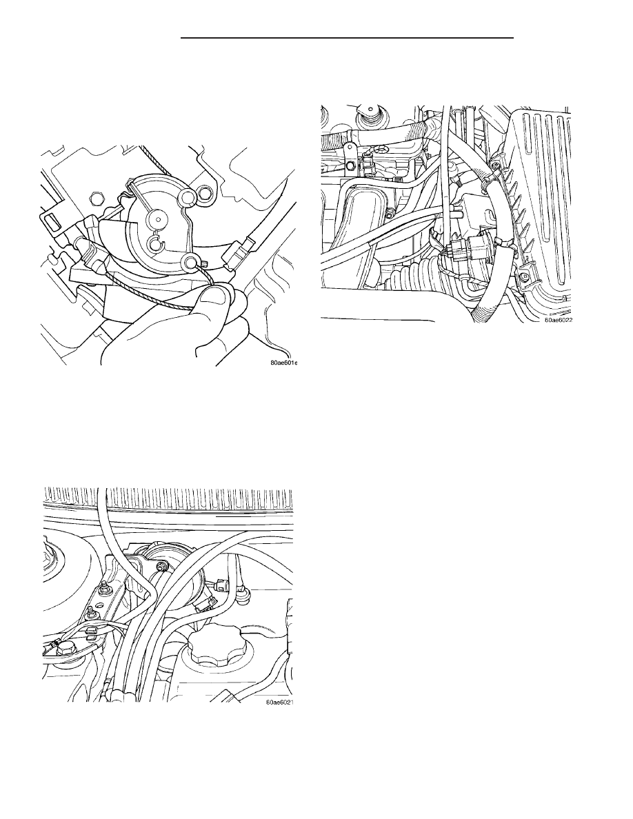
(2) Remove the throttle cable cover.
(3) Remove speed control cable from throttle lever
by sliding clasp out of the hole (Fig. 3).
(4) Lift the retaining tab on the throttle cable and
slide cable out of bracket. Lift the retaining tab on
the speed control cable and slide cable out of bracket.
(5) Disconnect electrical connector from servo.
(6) Disconnect vacuum hose from servo
(7) Remove 2 nuts retaining bracket to servo (Fig.
4).
(8) Remove push nuts holding cable housing to
servo.
(9) Remove retaining clip holding cable to servo
(Fig. 5).
INSTALLATION
(1) Install retaining clip to cable at servo.
(2) Slide cable bell housing over servo mounting
studs.
(3) Install servo mounting studs into bracket.
(4) Install 2 nuts at cable to servo and servo
bracket, tighten to 7 N·m (60 in. lbs.).
(5) Connect electrical connector to servo.
(6) Connect vacuum hose to servo
(7) Rotate the throttle lever forward to the wide
open position and install speed control cable clasp.
(8) Slide speed control cable into throttle cable
bracket and engage retaining tab. Slide throttle cable
into throttle cable bracket and engage retaining tab.
(9) Install the Throttle cable cover.
(10) Connect the negative battery cable.
SERVO
DESCRIPTION
The servo unit consists of a solenoid valve body,
and a vacuum chamber. The solenoid valve body con-
tains three solenoids:
• Vacuum
• Vent
• Dump
The vacuum chamber contains a diaphragm with a
cable attached to control the throttle linkage.
OPERATION
The PCM controls the solenoid valve body. The
solenoid valve body controls the application and
release of vacuum to the diaphragm of the vacuum
Fig. 3 Disconnecting Throttle Cable
Fig. 4 Speed Control Servo
Fig. 5 Speed Control Cable
8P - 4
SPEED CONTROL
PL/SRT-4
CABLE (Continued)