Dodge Neon / Neon SRT-4. Manual - part 109
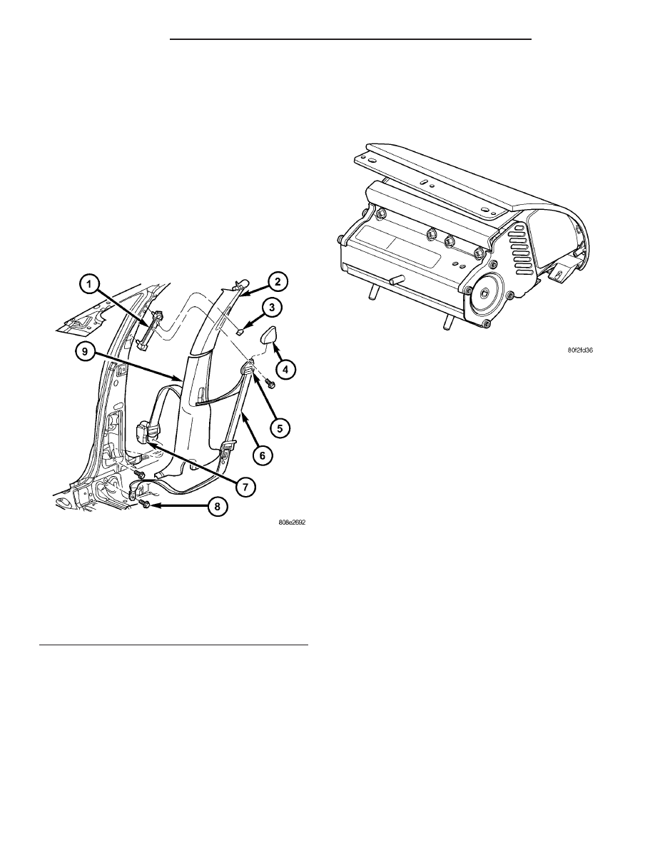
FRONT SEAT BELT &
RETRACTOR
REMOVAL
CAUTION: Front seat belt assemblies must be
replaced after a collision.
(1) Remove B-pillar trim.
(2) Remove bolt attaching seat belt retractor to
B-pillar (Fig. 13).
(3) Disconnect the wire connector to the retractor.
(4) Remove seat belt retractor from vehicle.
INSTALLATION
CAUTION: Front seat belt assemblies must be
replaced after a collision.
(1) Connect the wire connector to the retractor.
(2) Install seat belt retractor into vehicle.
(3) Install bolt attaching seat belt retractor to
B-pillar. Tighten seat belt anchor bolt to 40 N·m (30
ft. lbs.) torque.
(4) Install B-pillar trim.
PASSENGER AIRBAG
DESCRIPTION
The passenger airbag (Fig. 14) is located behind
the passenger airbag cover, between the glove box
and instrument panel top cover.
The passenger airbag includes an aluminum hous-
ing within which the cushion and inflator are
mounted and sealed. Two stamped metal brackets,
one on each end of the housing, enclose the cushion
and inflator. The mounting scheme consists of two
weld studs and a bracket with two tabs off the bot-
tom of the housing.
Following a passenger airbag deployment, the pas-
senger airbag and the passenger airbag cover must
be replaced. If inspection reveals that the passenger
airbag mounting points on the instrument panel have
been cracked or damaged, the instrument panel
assembly must also be replaced. The passenger air-
bag cannot be repaired, and must be replaced if
deployed or in any way damaged.
OPERATION
The hybrid-type inflator assembly includes a small
canister of highly compressed argon gas. The inflator
seals the hole in the airbag cushion so it can dis-
charge the gas it produces directly into the cushion
when supplied with the proper electrical signal. Fol-
lowing an airbag deployment, the airbag cushion
quickly deflates by venting this gas through the
porous fabric material used on each end panel of the
airbag cushion.
The passenger airbag is secured with nuts to the
instrument panel beneath the instrument panel top
pad and above the glove box opening.
Fig. 13 FRONT SEAT BELT RETRACTOR
1 - FRONT SEAT BELT ADJUSTER
2 - UPPER B-PILLAR TRIM PANEL
3 - ADJUSTER BUTTON
4 - TURNING LOOP COVER
5 - TURNING LOOP
6 - SEAT BELT
7 - SEAT BELT RETRACTOR
8 - ANCHOR BOLT
9 - LOWER B-PILLAR TRIM PANEL
Fig. 14 PASSENGER AIRBAG
8O - 12
RESTRAINTS
PL/SRT-4