Dodge Neon / Neon SRT-4. Manual - part 105
 

  Index      Dodge     Dodge Neon / Neon SRT-4 - service repair manual 2005 year


Search            


Content   ..  103  104  105  106   ..


Dodge Neon / Neon SRT-4. Manual - part 105


(5) Remove the two screws that secure the power

seat switch to the inside of the outboard seat cushion
side shield.

(6) Remove the power seat switch from the out-

board seat cushion side shield.

INSTALLATION

(1) Position the power seat switch onto the out-

board seat cushion side shield.

(2) Install and tighten the two screws that secure

the power seat switch to the inside of the outboard
seat cushion side shield. Tighten the screws to 1.5
N·m (14 in. lbs.).

(3) Reconnect the power seat wire harness connec-

tor to the power seat switch connector receptacle.

(4) Position the outboard seat cushion side shield

onto the seat cushion frame

(5) Install and tighten the three screws that secure

the outboard seat cushion side shield to the seat

cushion frame. Tighten the screws to 1.5 N·m (14 in.
lbs.).

(6) Reconnect the battery negative cable.

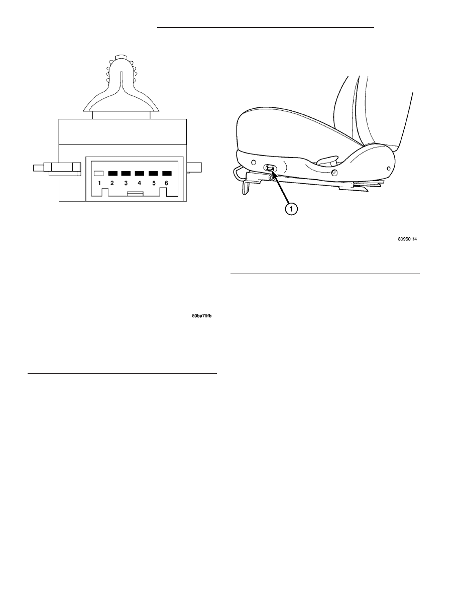
Fig. 3 Power Seat Switch Electrical Pin I.D.

TESTING POWER SEAT SWITCH

SWITCH POSITION

CONTINUITY BETWEEN

Off

2-4, 3-5

UP

3-5, 4-6

DOWN

2-4, 3-6

Fig. 4 POWER SEAT SWITCH

1 - PL POWER SEAT SWITCH

8N - 14

POWER SEAT SYSTEM

PL/SRT-4

DRIVER SEAT SWITCH (Continued)

SEAT TRACK

DESCRIPTION

There is one motor that operates the power seat

track (Fig. 5). The motor is connected to a worm-
drive gearbox that moves the seat adjuster accord-
ingly. The drivers front seat can be raised or lowered
using the power seat switch, located on the seat
cushion side shield. When the seat switch is pushed
to the Up or Down position the seat will move up or
down.

The motor contains a self-resetting circuit breaker

to protect it from overload. Consecutive or frequent
resetting of the circuit breakers must not be allowed
to continue, or the motors may be damaged.

The power seat track cannot be repaired, and is

serviced only as a complete unit. If any component in
this unit is faulty or damaged, the entire power seat
track unit must be replaced.

OPERATION

When a power seat switch is actuated, a battery

feed and a ground path are applied through the
switch contacts to the appropriate motor. The motor
and drive operate to move the seat in the selected
direction until the power seat switch is released, or
until the travel limit of the power seat track adjuster
is reached. When the power seat switch is moved in
the opposite direction, the battery feed and ground
path to the motor are reversed through the switch
contacts. This causes the motor and drive to run in
the opposite direction.

DIAGNOSIS AND TESTING - SEAT TRACK

Refer to the appropriate wiring information. The

wiring information includes wiring diagrams, proper
wire and connector repair procedures, further details
on wire harness routing and retention, as well as
pin-out and location views for the various wire har-
ness connectors, splices and grounds.

Operate the power seat switch to move the seat

motor in each direction. The seat should move in each
of the selected directions. If the power seat track fails
to operate in only one direction, move the seat a short
distance in the opposite direction and test again to be
certain that the adjuster is not at its travel limit. If
the power seat track still fails to operate in only one
direction, begin by testing the power seat switch for
the inoperative seat. If the power seat track fails to
operate in more than one direction, proceed as follows:

(1) Test the circuit breaker in the Junction Block

(JB). If OK, Step 2. If not OK, replace the faulty cir-
cuit breaker.

(2) Remove the power seat switch from the seat.

Check for battery voltage at the fused B(+) circuit
cavity of the power seat wire harness connector for
the power seat switch. If OK, go to Step 3. If not OK,
repair the open fused B(+) circuit between the power
seat switch and the JB as required.

(3) Check for continuity between the ground cir-

cuit cavity of the power seat wire harness connector
for the power seat switch and a good ground. There
should be continuity. If OK, Step 4. If not OK, repair
the open ground circuit to ground as required.

(4) Test the power seat switch. If the switch tests

OK, test the circuits of the power seat wire harness
for the inoperative power seat motor(s) between the
power seat switch and the inoperative motor for
shorts or opens. If the circuits check OK, replace the
faulty power seat track. If the circuits are not OK,
repair the power seat wire harness as required.

REMOVAL

(1) Remove the power seat from the vehicle. (Refer

to 23 - BODY/SEATS/SEAT - REMOVAL)

(2) Disengage and disconnect the power seat wire

harness from the power seat track.

(3) Remove the power seat track retaining fasten-

ers and remove the power seat track from the seat.

INSTALLATION

(1) Reinstall the power seat track onto the seat

cushion frame.

(2) Secure and connect the power seat wire har-

ness on the power seat track.

(3) Reinstall the power seat assembly into the

vehicle as a unit. (Refer to 23 - BODY/SEATS/SEAT -
INSTALLATION).

(4) Reconnect the battery negative cable.

Fig. 5 POWER SEAT TRACK

PL/SRT-4

POWER SEAT SYSTEM

8N - 15

POWER WINDOWS

TABLE OF CONTENTS

page

page

POWER WINDOWS

DESCRIPTION

. . . . . . . . . . . . . . . . . . . . . . . . . 16

OPERATION

. . . . . . . . . . . . . . . . . . . . . . . . . . . 16

DIAGNOSIS AND TESTING - POWER

WINDOWS

. . . . . . . . . . . . . . . . . . . . . . . . . . . 16

WINDOW MOTOR

DESCRIPTION

. . . . . . . . . . . . . . . . . . . . . . . . . 17

OPERATION

. . . . . . . . . . . . . . . . . . . . . . . . . . . 17

REMOVAL

. . . . . . . . . . . . . . . . . . . . . . . . . . . . . 17

INSTALLATION

. . . . . . . . . . . . . . . . . . . . . . . . . 17

WINDOW SWITCH

DIAGNOSIS AND TESTING - WINDOW

SWITCH

. . . . . . . . . . . . . . . . . . . . . . . . . . . . 17

REMOVAL

. . . . . . . . . . . . . . . . . . . . . . . . . . . . . 17

INSTALLATION

. . . . . . . . . . . . . . . . . . . . . . . . . 17

POWER WINDOWS

DESCRIPTION

The power window system allows each of the front

door windows to be raised and lowered electrically by
actuating a switch on each front door trim panel. A
master switch on the driver’s door allows the driver
to raise or lower each of the front door windows. The
power window system receives battery feed through a
fuse in the Power Distribution Center (PDC), only
when the ignition switch is in the RUN or ACCES-
SORY position.

OPERATION

WINDOW SWITCH

The power window switches control the battery

and ground feeds to the power window motors.

WINDOW MOTOR

Front door window lift motors use permanent type

magnets. The B+ and ground applied at the motor
terminal pins will cause the motor to rotate in one
direction. Reversing current through the motor ter-
minals will cause the motor to rotate in the opposite
direction.

Refer to the appropriate wiring information.

DIAGNOSIS AND TESTING - POWER
WINDOWS

WIRING VOLTAGE TEST

The following wiring test determines whether or

not voltage is continuous through the body harness
to the switch.

(1) Remove the power window switch and bezel.
(2) Disconnect wire connector from back of power

window switch.

(3) Switch ignition to the ON position.

(4) Connect the clip end of a 12 volt test light to

Pin 4 of the window switch harness connector. Touch
the test light probe to Pin 3.

• If the test light illuminates, the wiring circuit

between the battery and switch is OK.

• If the lamp does not illuminate, first check the

30 amp circuit in the fuse block. If circuit breaker is
OK, then check for a broken wire.

Refer to the appropriate wiring information.

POWER WINDOW MOTOR TEST

If the power window motor is receiving proper cur-

rent and ground and does not operate, proceed with
motor test. Refer to the appropriate wiring informa-
tion.

(1) Remove front door trim panel as necessary to

gain access to power window motor wire connector.

(2) Disconnect power window motor connector from

motor.

(3) Using two jumper wires, connect one to a bat-

tery (+) source and the other to a good ground (-).

(4) Connect the Negative (-) jumper probe to one of

the motor connector terminals.

(5) Momentarily touch the Positive (+) jumper

probe to the other motor connector terminal.

When positive probe is connected the motor should

rotate in one direction to either move window up or
down. If window is all the way up or down the motor
will grunt and the inner door panel will flex when
actuated in that one direction.

(6) Reverse jumper probes at the motor connector

terminals and window should now move in opposite
direction. If window does not move or grunt, replace
the motor.

If window moved completely up or down, reverse

the jumper probes and cycle window to the opposite
position to verify full operation.

If motor grunts and does not move, verify that reg-

ulator is not binding.

8N - 16

POWER WINDOWS

PL/SRT-4

WINDOW MOTOR

DESCRIPTION

The power window system allows each of the front

door windows to be raised and lowered electrically by
actuating a switch on each respective door. A master
switch on the driver side door trim panel allows the
driver to raise or lower each of the front door win-
dows.

OPERATION

The window lift motors are of the permanent mag-

net type. A battery positive and negative connection
to either of the two motor terminals will cause the
motor to rotate in one direction. Reversing current
through these same two connections will cause the
motor to rotate in the opposite direction. Each motor
is grounded through the master switch.

REMOVAL

(1) Disconnect and isolate the battery negative

cable.

(2) Move the window to the full-up position, if pos-

sible.

(3) Remove front door trim panel (Refer to 23 -

BODY/DOOR - FRONT/TRIM PANEL - REMOVAL).

(4) Remove front door water shield.
(5) Remove

three

screws

to

front

door

radio

speaker so that motor has room to pivot.

(6) Pivot window motor out of door panel.
(7) Remove three motor retaining screws to drive

cable.

(8) Remove motor from drive cable assembly.

INSTALLATION

(1) Install motor to the cable drive assembly.
(2) Install motor retaining screws to drive cable.
(3) Install the screws to the front door radio

speaker.

(4) Install the front door water shield.
(5) Install the front door trim panel. (Refer to 23 -

BODY/DOOR - FRONT/TRIM PANEL - INSTALLA-
TION).

(6) Reconnect the battery negative cable.

WINDOW SWITCH

DIAGNOSIS AND TESTING - WINDOW SWITCH

Remove the switch from its mounting, (Refer to 8 -

ELECTRICAL/POWER

WINDOWS/POWER

WIN-

DOW SWITCH - REMOVAL). Using an ohmmeter,

test the window switch for continuity in all positions
Refer to Power Window Switch Continuity table to
determine if continuity is correct (Fig. 1). If the cor-
rect results are not obtained, replace the switch.

POWER WINDOW SWITCH CONTINUITY

SWITCH POSITION

CONTINUITY BETWEEN

OFF

PIN 1 AND 4
PIN 2 AND 5
PIN 3 AND 8

DOWN

PIN 1 AND 4
PIN 4 AND 8
PIN 2 AND 5

UP

PIN 1 AND 4
PIN 4 AND 5
PIN 3 AND 8

REMOVAL

(1) Disconnect and isolate the battery negative

cable.

(2) Using a trim stick (special tool #C-4755) or

equivalent, gently pry up on window switch bezel
and remove from door trim panel.

(3) Disconnect wire connector from switch.
(4) Remove two switch retaining screws.

INSTALLATION

(1) install the switch retaining screws.
(2) Reconnect the wire connector to the switch.
(3) Insert switch into the door trim panel.
(4) Reconnect the battery negative cable.

Fig. 1 POWER WINDOW SWITCH

PL/SRT-4

POWER WINDOWS

8N - 17


Content   ..  103  104  105  106   ..