Dodge Neon / Neon SRT-4. Manual - part 87
DIAGNOSIS AND TESTING
REAR WINDOW DEFOGGER SWITCH
WARNING: On vehicles equipped with airbags, dis-
able the airbag system before attempting any steer-
ing wheel, steering column, or instrument panel
component diagnosis or service. Disconnect and
isolate the battery negative (ground) cable, then
wait two minutes for the airbag system capacitor to
discharge before performing further diagnosis or
service. This is the only sure way to disable the air-
bag system. Failure to take the proper precautions
could result in an accidental airbag deployment and
possible personal injury or death.
NOTE: The rear window defogger switch may be
tested in the vehicle or out of the vehicle, on a
workbench.
NOTE: For circuit descriptions and diagrams of the
rear window defogger system, refer to 8W - WIRING
DIAGRAM INFORMATION.
IN-VEHICLE TESTING
(1) Remove the rear window defogger switch from
the instrument panel, but leave the switch connected
(Refer to 23 - BODY/INSTRUMENT PANEL/ACCES-
SORY SWITCH BEZEL - REMOVAL).
(2) Turn the ignition switch to the On position.
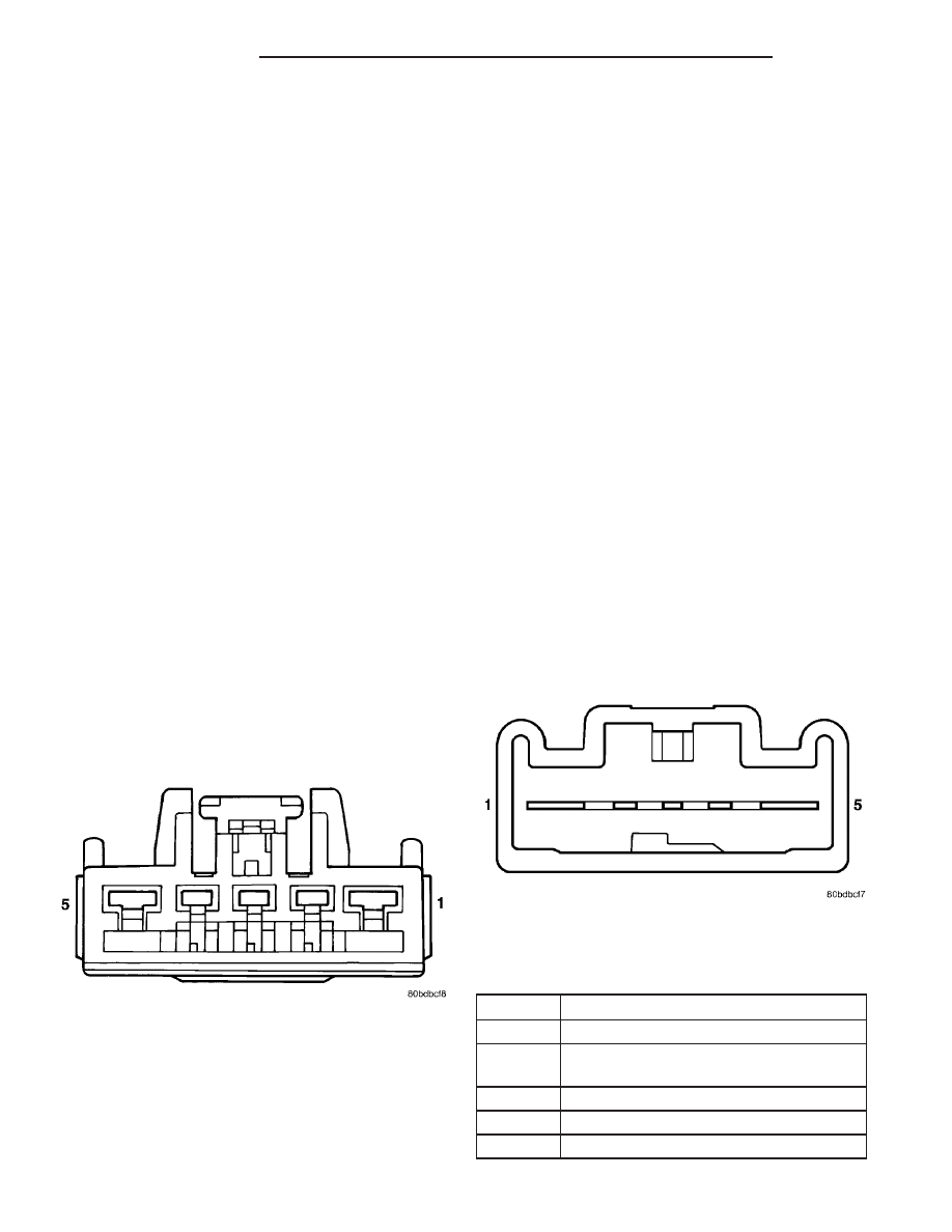
(3) Using a voltmeter, check for battery voltage at
Pin 1 and 2 of the rear window defogger switch (Fig.
5).
(a) If OK, go to Step 4.
(b) If NOT OK, check the 10 amp fuse 6 in the
junction block (JB) and the 40 amp fuse 8 in the
power distribution center (PDC). If fuses are OK,
check the wiring circuits. Refer to 8W - WIRING
DIAGRAM INFORMATION.
(4) Check Pin 5, with rear window defogger switch
in the On position there should be battery voltage
and no voltage in the Off position.
(a) If OK, go to Step 5.
(b) If NOT OK, no voltage in the On position or
voltage in the Off position. Replace the rear win-
dow defogger switch (Refer to 23 - BODY/INSTRU-
MENT PANEL/ACCESSORY SWITCH BEZEL -
INSTALLATION).
(5) Press the rear window defogger switch to the
On position. The indicator lamp should come on and
remain on for approximately ten minutes. If the indi-
cator lamp fails to light or no voltage is present,
replace the rear window defogger switch (Refer to 23
-
BODY/INSTRUMENT
PANEL/ACCESSORY
SWITCH BEZEL - INSTALLATION).
BENCH TESTING
(1) Remove the rear window defogger switch (Refer
to 23 - BODY/INSTRUMENT PANEL/ACCESSORY
SWITCH BEZEL - REMOVAL).
(2) With switch removed from vehicle, use a
jumper wire and connect a 12 volt supply to Pin 1
and 2. Using a third jumper wire, ground Pin 3.
Refer to (Fig. 6) and the Rear Window Defogger
Switch and Harness Connector Pin Call-Out table.
(3) Follow the same procedures used for IN-VEHI-
CLE TESTING, except for step Step 2.
REAR WINDOW DEFOGGER SWITCH AND
HARNESS CONNECTOR PIN CALL-OUT
PIN
FUNCTION
1
FUSED B+
2
FUSED IGNITION SWITCH OUTPUT
(RUN)
3
GROUND
4
PANEL LAMPS DRIVER
5
PANEL LAMPS DRIVER
Fig. 5 Rear Window Defogger Switch Harness
Connector
Fig. 6 Rear Window Defogger Switch Connector
8G - 4
HEATED GLASS
PL/SRT-4
REAR WINDOW DEFOGGER SWITCH (Continued)