Dodge Neon / Neon SRT-4. Manual - part 58
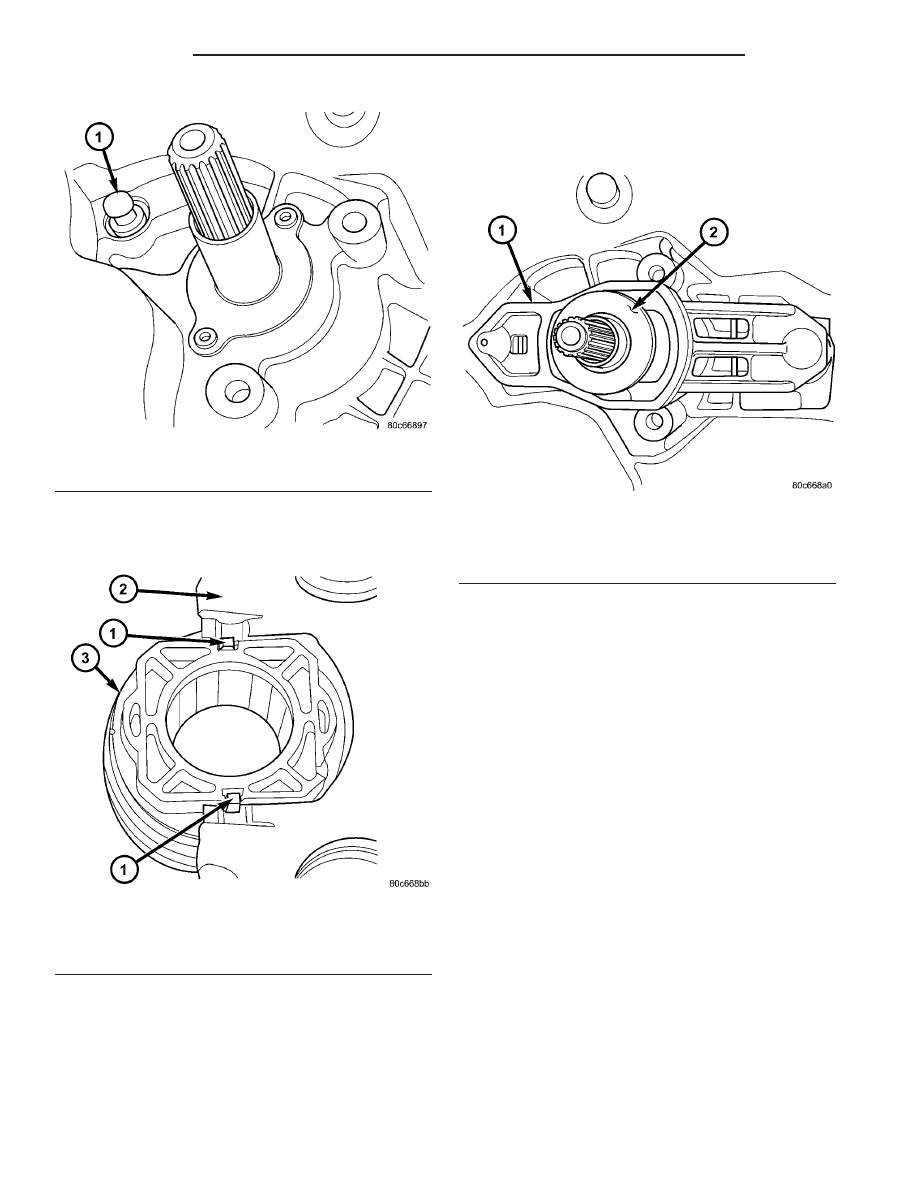
(2) Install clutch release bearing to lever. Apply
grease to interface points. Make sure release bearing
retainers engage lever pocket as shown in (Fig. 24).
(3) Apply grease to pivot ball, and on release lever
at slave cylinder contact point.
(4) Install clutch release bearing/lever assembly
into position by sliding bearing onto input bearing
retainer, and using moderate hand pressure to seat
release lever to pivot ball (Fig. 25). A “pop” sound
should be heard. Verify proper engagement by lightly
pulling outward on lever at pivot ball location, and
then actuating lever and bearing to ensure proper
operation.
(5) Reinstall transaxle assembly (Refer to 21 -
TRANSMISSION/TRANSAXLE/T 850 MANUAL -
INSTALLATION)
MASTER CYLINDER-LHD
DESCRIPTION
NOTE: A one-piece master/slave cylinder assembly
is used on T350 models. If the master cylinder
requires replacement, the master AND slave cylin-
ders must be replaced with a two-piece system.
The LHD clutch master cylinder mounts to the
dash panel (Fig. 26). The master cylinder consists of
an adjustable push rod, a piston and cylinder hous-
ing, a remote fluid reservoir, an interconnecting
hydraulic tube, and an integral slave cylinder (Fig.
27).
Fig. 23 Pivot Ball Orientation (RHD)
1 - PIVOT BALL (1)
Fig. 24 Release Bearing-to-Lever
1 - RETAINER (2)
2 - RELEASE LEVER
3 - RELEASE BEARING
Fig. 25 Release Bearing and Lever—2.4L Turbo
Models
1 - RELEASE LEVER
2 - RELEASE BEARING
6 - 16
CLUTCH
PL/SRT-4
CLUTCH RELEASE BEARING AND LEVER (Continued)