Dodge Neon / Neon SRT-4. Manual - part 23
CAMBER AND CASTER
Front and rear camber and caster settings on this
vehicle are determined at the time the vehicle is
designed, by the location of the vehicle’s suspension
components. This is referred to as Net Build. The
result is no required adjustment of camber and
caster after the vehicle is built or when servicing the
suspension components. Thus, when performing a
wheel alignment, caster and camber are not normally
considered adjustable angles. Camber and caster
should be checked to ensure they meet vehicle speci-
fications.
If either front or rear camber is found not to meet
alignment specifications, it can be adjusted using an
available camber adjustment bolt package. Before
installing a camber adjustment bolt package on a
vehicle found to be outside the specifications, inspect
the suspension components for any signs of damage
or bending.
No adjustment can be made to the caster setting
on this vehicle. If the vehicle’s caster is not within
alignment specifications, check for damaged suspen-
sion components or body parts.
CAUTION: Do not attempt to adjust the vehicles
wheel alignment by heating or bending any of the
suspension components.
CAMBER ADJUSTMENT BOLT PACKAGE INSTALLATION
The camber adjustment bolt package contains new
bolts and nuts for attaching the strut clevis bracket
to the steering knuckle. The bolts contained in the
package are slightly undersize allowing for move-
ment between the strut clevis bracket and the steer-
ing knuckle. The movement allowed by the undersize
bolts provides approximately one degree of camber
adjustment per side of the vehicle. To install and
adjust the camber adjustment bolt package, follow
the procedure below.
CAUTION: There are separate camber adjustment
bolt packages for the front and rear of the vehicle.
Be sure to use the correct package.
(1) Raise the vehicle until its tires are not support-
ing the weight of the vehicle.
CAUTION: The knuckle to strut assembly attaching
bolt shanks are serrated and must not be turned
during removal. Remove the nuts while holding the
bolts stationary.
(2) Remove the wheel and tire assembly at the
strut requiring modification.
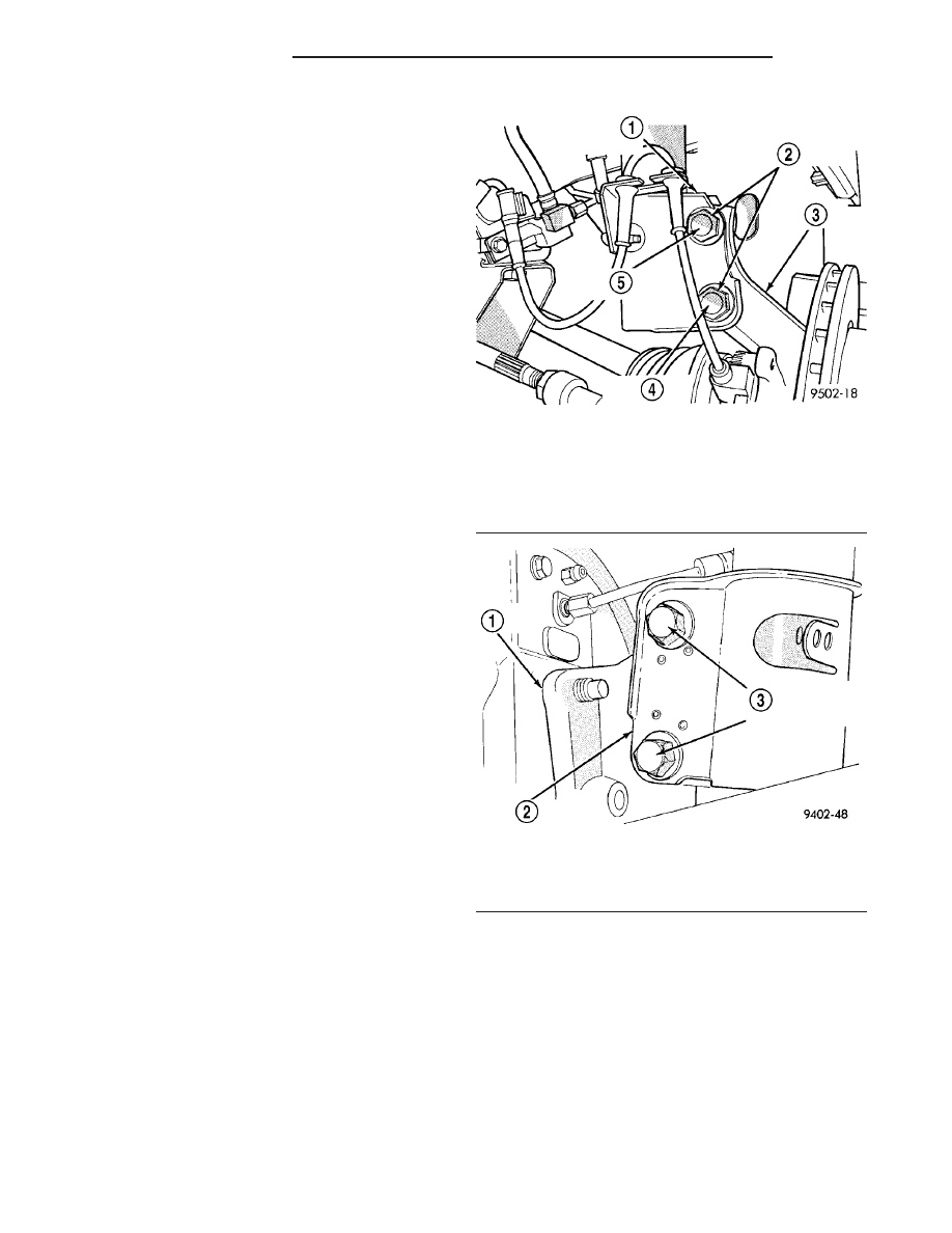
(3) Remove the original upper bolt attaching the
strut clevis bracket to the knuckle (Fig. 7) (Fig. 8).
(4) Install a bolt from the adjustment package into
the hole where the original bolt was removed. Install
the bolt from the rear.
(5) Install a nut provided in adjustment package
on the replacement bolt. Tighten the nut until it’s
snug, but still allowing the knuckle to slide in the
clevis bracket.
(6) Remove the original lower bolt.
(7) Install a bolt from the adjustment package into
the bottom hole of the strut clevis bracket. Install the
bolt from the rear.
Fig. 7 Front Strut Clevis Bracket Attaching Bolts
1 - STRUT CLEVIS BRACKET
2 - STRUT CLEVIS BRACKET TO STEERING KNUCKLE
ATTACHING BOLTS
3 - STEERING KNUCKLE
4 - LOOSEN THIS BOLT
5 - REMOVE AND REPLACE THIS BOLT
Fig. 8 Rear Strut Clevis Bracket Attaching Bolts
1 - KNUCKLE
2 - STRUT ASSEMBLY CLEVIS BRACKET
3 - CLEVIS BRACKET TO KNUCKLE ATTACHING BOLTS
2 - 54
WHEEL ALIGNMENT
PL/SRT-4
WHEEL ALIGNMENT (Continued)