Dodge Nitro. Manual - part 970
 

  Index      Dodge     Dodge Nitro - service repair manual 2007 year


Search            


Content   ..  968  969  970  971   ..


Dodge Nitro. Manual - part 970


3. If the switch fails any of the tests, replace the ineffective right multi-function switch as required. If the 

switch tests okay, but the switch input to the Steering Control Module (SCM) remains incorrect, be 
certain to check for a short or open in the jumper harness between the right multi-function switch and the 
SCM.  

REMOVAL 

RIGHT MULTI-FUNCTION SWITCH 

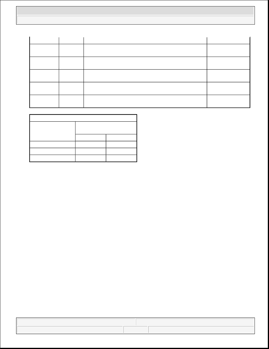
2
Front Delay 
3

OPEN

OPEN

CLOSED

Front Delay 
4

OPEN

CLOSED

CLOSED

Front Delay 
5

OPEN

CLOSED

OPEN

Front Wiper 
Low

OPEN

OPEN

OPEN

Front Wiper 
High

CLOSED

OPEN

OPEN

CONTROL SLEEVE FUNCTION TESTS 

FUNCTION 

BETWEEN PIN 7 

(GROUND) AND PINS 

Off

CLOSED

OPEN

Rear Wipe

CLOSED

CLOSED

Rear Wash

OPEN

CLOSED

WARNING:

To avoid serious or fatal injury on vehicles equipped with airbags, disable 
the supplemental restraint system before attempting any steering wheel, 
steering column, airbag, occupant classification system, seat belt 
tensioner, impact sensor, or instrument panel component diagnosis or 
service. Disconnect and isolate the battery negative (ground) cable, then 
wait two minutes for the system capacitor to discharge before performing 
further diagnosis or service. This is the only sure way to disable the 
supplemental restraint system. Failure to take the proper precautions 
could result in accidental airbag deployment.


2007 Dodge Nitro R/T 

2007 ACCESSORIES AND EQUIPMENT Wipers/Washers - Service Information - Nitro


Fig. 10: Right Multi-Function Switch 
Courtesy of CHRYSLER LLC 

1. Disconnect and isolate the battery negative cable.  

2. Remove both the upper and lower shrouds from the steering column. Refer to REMOVAL .  

3. Remove the screw (2) that secures the right multi-function switch (1) to the mounting bracket integral to 

the right side of the clockspring (3) on the steering column.  

4. Slide the switch away from the clockspring far enough to disengage the slide tabs on the switch housing 

from the channel formations in the mounting bracket. 

Fig. 11: Identifying Jumper Wire Harness Connector, Right Multi-Function Switch & Clockspring
Courtesy of CHRYSLER LLC
 

5. Disconnect the jumper wire harness connector (1) from the connector receptacle on the inboard end of the 

right multi-function switch (2).  

6. Remove the switch from the clockspring (3).  

INSTALLATION 

RIGHT MULTI-FUNCTION SWITCH 


2007 Dodge Nitro R/T 

2007 ACCESSORIES AND EQUIPMENT Wipers/Washers - Service Information - Nitro


Fig. 12: Identifying Jumper Wire Harness Connector, Right Multi-Function Switch & Clockspring 
Courtesy of CHRYSLER LLC 

1. Position the right multi-function switch (2) close enough to the mounting bracket (3) integral to the right 

side of the clockspring to reconnect the jumper wire harness connector (1) to the connector receptacle on 
the inboard side of the switch housing.  

2. Align the slide tabs on the switch housing with the channel formations integral to the clockspring 

mounting bracket, then slide the switch into the bracket until it is firmly seated. 

Fig. 13: Right Multi-Function Switch

WARNING:

To avoid serious or fatal injury on vehicles equipped with airbags, disable 
the supplemental restraint system before attempting any steering wheel, 
steering column, airbag, occupant classification system, seat belt 
tensioner, impact sensor, or instrument panel component diagnosis or 
service. Disconnect and isolate the battery negative (ground) cable, then 
wait two minutes for the system capacitor to discharge before performing 
further diagnosis or service. This is the only sure way to disable the 
supplemental restraint system. Failure to take the proper precautions 
could result in accidental airbag deployment.


2007 Dodge Nitro R/T 

2007 ACCESSORIES AND EQUIPMENT Wipers/Washers - Service Information - Nitro


Courtesy of CHRYSLER LLC 

3. Install and tighten the screw (2) that secures the mounting tab on the back of the right multi-function 

switch (1) to the mounting bracket on the clockspring (3). Tighten the screw to 1 N.m (10 in. lbs.).  

4. Reinstall the upper and lower shrouds onto the steering column. Refer to INSTALLATION .  

5. Reconnect the battery negative cable.  

WASHER HOSES/TUBES 

DESCRIPTION 

FRONT WASHER PLUMBING 

Fig. 14: Left-Hand Drive 
Courtesy of CHRYSLER LLC 


2007 Dodge Nitro R/T 

2007 ACCESSORIES AND EQUIPMENT Wipers/Washers - Service Information - Nitro


Content   ..  968  969  970  971   ..