Dodge Nitro. Manual - part 798
 

  Index      Dodge     Dodge Nitro - service repair manual 2007 year


Search            


Content   ..  796  797  798  799   ..


Dodge Nitro. Manual - part 798


functions.  

Horn Switch Support - On vehicles without the optional EVIC, the EMIC receives a hard wired input 
from the horn switch on the steering wheel. On vehicles with the optional EVIC, the EMIC receives 
electronic horn switch status messages from the Steering Wheel Switch Module (SWSM) over the LIN 
bus. In either case, the EMIC then provides electronic horn request messages over the CAN data bus to 
support the horn function.  

Interior Lamp Load Shedding - The EMIC provides a battery saver feature which will automatically 
turn OFF all interior lamps if they remain ON after a timed interval of about ten minutes.  

Interior Lighting Control - The EMIC monitors electronic messages and hard wired inputs from the 
reading lamp switches, the Sentry Key REmote Entry Module (SKREEM) (also known as the Wireless 
Control Module/WCM), the Steering Control Module (SCM) and the Totally Integrated Power Module 
(TIPM) to provide courtesy lamp control. This includes support for timed illuminated entry with theater-
style fade-to-OFF and courtesy illumination DEFEAT features.  

Local Interface Network Master Module - The EMIC is the master module for the LIN data bus. In this 
role it gathers information from the compass sensor, the Heated Seat Module (HSM), the instrument 
panel switch pod, the Steering Wheel Switch Module (SWSM), the SCM and the remote compass 
module, then either acts on that information directly or places electronic messages on the CAN data bus 
for use by other modules  

Panel Lamps Dimming Control - The EMIC monitors electronic dimming level messages received 
from the panel lamps dimmer switch input to the SCM over the LIN data bus, then provides both a hard 
wired 12-volt Pulse-Width Modulated (PWM) output and electronic message outputs over the CAN data 
bus and the LIN data bus that synchronizes the dimming level of all panel lamps dimmer controlled lamps 
with that of the cluster general illumination lighting.  

Wiper and Washer Switch Support - The EMIC monitors electronic wiper switch and washer switch 
status
 messages from the SCM on the steering column over the LIN data bus and transmits the 
appropriate electronic wiper and washer request messages to the TIPM over the CAN data bus to 
support the wiper and washer system functions, including the headlamps-on with wipers programmable 
feature.  

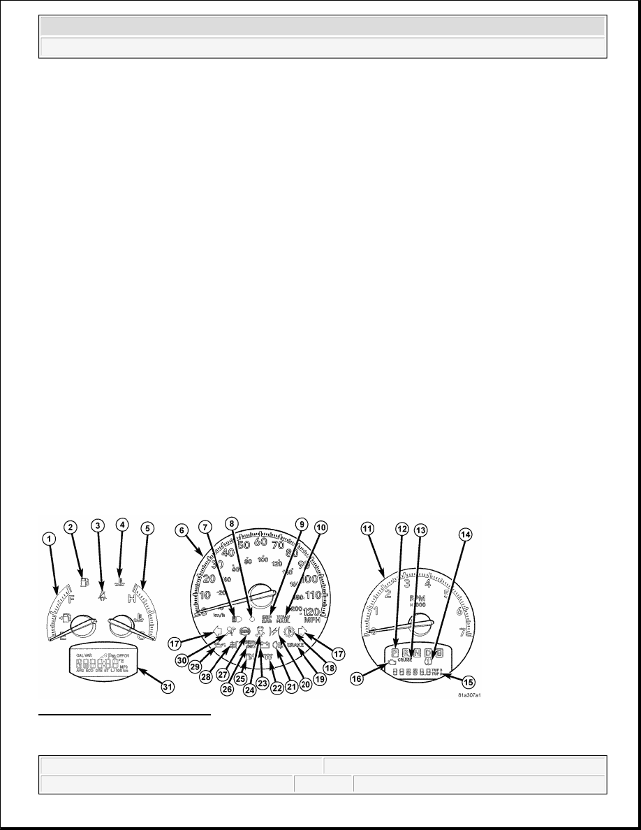
Fig. 3: Analog Gauge Indicators 
Courtesy of CHRYSLER LLC 

The EMIC houses four analog gauges and has provisions for up to 25 indicators. Some of the EMIC indicators 


2007 Dodge Nitro R/T 

2007 ACCESSORIES AND EQUIPMENT Instrument Cluster - Service Information - Nitro


are automatically configured when the EMIC is connected to the vehicle electrical system for compatibility with 
certain optional equipment or equipment required for regulatory purposes in certain markets. While each EMIC 
may have provisions for indicators to support every available option, the configurable indicators will not be 
functional in a vehicle that does not have the equipment that an indicator supports. 

The EMIC includes the following analog gauges: 

Engine Temperature Gauge (5)  

Fuel Gauge (1)  

Speedometer (6)  

Tachometer (11)  

The EMIC includes the following VFD display units: 

Odometer Display (15) - includes Cruise indicator (13), Gear Selector indicator (12), Malfunction 
Indicator Lamp (MIL) (16) and Tire Pressure Monitor (TPM) indicator (14).  

Compass-Temperature or Electronic Vehicle Information Center Display (31)  

The EMIC includes provisions for the following indicators: 

Airbag Indicator (30)  

Ajar Indicators (15 or 31) - text in odometer display for doors and liftgate in clusters without EVIC, or 
icons in the EVIC display of vehicles with that option  

Antilock Brake System (ABS) Indicator (27)  

Brake Indicator (19) - text only for U.S. market, icon only for markets outside U.S.  

Charging Indicator (23)  

Cruise Indicator (13)  

Electronic Stability Program (ESP)/Brake Assist System (BAS) Indicator (9)  

Electronic Throttle Control (ETC) Indicator (20)  

Engine Coolant Temperature Indicator (4)  

Front Fog Lamp Indicator (28) - with optional front fog lamps only  

Gas Cap Indicator - textual message in odometer display (15)  

Gear Selector Indicator (12) - with automatic transmission only  

High Beam Indicator (7)  

Low Fuel Indicator (2)  

Low Oil Pressure Indicator (29)  

Malfunction Indicator Lamp (MIL) (16)  

Rear Fog Lamp Indicator (21) - in markets where rear fog lamps are available only  

Seat Belt Indicator (3)  

Security Indicator (8)  

Service Four-Wheel Drive (4WD) Indicator (26) - with optional four-wheel drive system only 


2007 Dodge Nitro R/T 

2007 ACCESSORIES AND EQUIPMENT Instrument Cluster - Service Information - Nitro


Tire Pressure Monitor (TPM) Indicator (14)  

Tow/Haul Indicator (10) - with automatic transmission only  

Traction Control/Electronic Stability Program (ESP) Indicator (24)  

Transmission Temperature Indicator (18) - with automatic transmission only  

Turn Signal (Right and Left) Indicators (17)  

Wait-To-Start Indicator (22) - with diesel engine only  

Water-In-Fuel Indicator (25) - with diesel engine only  

Each indicator in the EMIC, except those located within a VFD unit, is illuminated by a dedicated LED that is 
soldered onto the EMIC electronic circuit board. Cluster illumination is accomplished by several dimmable 
LED units, which illuminate each of the gauge dial faces for visibility when the exterior lighting is turned ON. 
These LED units are not available for service replacement and, if damaged or ineffective, the entire EMIC must 
be replaced. 

Hard wired circuitry connects the EMIC to the electrical system of the vehicle. These hard wired circuits are 
integral to several wire harnesses, which are routed throughout the vehicle and retained by many different 
methods. These circuits may be connected to each other, to the vehicle electrical system and to the EMIC 
through the use of a combination of soldered splices, splice block connectors, and many different types of wire 
harness terminal connectors and insulators. Refer to the appropriate wiring information. The wiring information 
includes wiring diagrams, proper wire and connector repair procedures, further details on wire harness routing 
and retention, as well as pin-out and location views for the various wire harness connectors, splices and 
grounds. 

The EMIC module for this vehicle is serviced only as a complete unit. The EMIC module cannot be adjusted or 
repaired. If a gauge, an LED unit, a VFD unit, the electronic circuit board, the circuit board hardware, the 
cluster overlay or the cluster housing are damaged or ineffective, the entire EMIC module must be replaced. 
The cluster lens and the cluster hood and mask unit are available for separate service replacement. 

OPERATION 

INSTRUMENT CLUSTER 

The Electro Mechanical Instrument Cluster (EMIC) in this vehicle also includes the hardware and software 
necessary to serve as the electronic body control module and is sometimes referred to as the Cab Compartment 
Node or CCN. The following information deals primarily with the instrument cluster functions of this unit. 
Additional details of the electronic body control functions of this unit may be found within the service 
information for the system or component that the EMIC controls. For example: Additional details of the audible 
warning functions of the EMIC are found within the Chime/Buzzer service information. 

The EMIC is designed to allow the vehicle operator to monitor the conditions of many of the vehicle 
components and operating systems. The gauges and indicators in the EMIC provide valuable information about 
the various standard and optional powertrains, fuel and emissions systems, cooling systems, lighting systems, 
safety systems and many other convenience items. The EMIC is installed in the instrument panel so that all of 
these monitors can be easily viewed by the vehicle operator when driving, while still allowing relative ease of 
access for service. 


2007 Dodge Nitro R/T 

2007 ACCESSORIES AND EQUIPMENT Instrument Cluster - Service Information - Nitro


The microprocessor-based EMIC hardware and software uses various inputs to control the gauges and 
indicators visible on the face of the cluster. Some of these inputs are hard wired, but most are in the form of 
electronic messages that are transmitted by other electronic modules over the Controller Area Network (CAN) 
data bus or the Local Interface Network (LIN) data bus. The EMIC is the master node for the LIN data bus. 
Refer to OPERATION . 

The EMIC microprocessor smooths the input data using algorithms to provide gauge readings that are accurate, 
stable and responsive to operating conditions. These algorithms are designed to provide gauge readings during 
normal operation that are consistent with customer expectations. However, when abnormal conditions exist 
such as high coolant temperature, the algorithm can drive the gauge pointer to an extreme position and the 
microprocessor can sound a chime through the on-board audible tone transducer to provide distinct visual and 
audible indications of a problem to the vehicle operator. The EMIC may also produce audible warnings for 
other electronic modules in the vehicle based upon electronic tone request messages received over the CAN or 
LIN data bus. Each audible warning is intended to provide the vehicle operator with an audible alert to 
supplement a visual indication. 

The EMIC circuitry operates on battery current received through a fused B(+) fuse on a non-switched fused B
(+) circuit, and on battery current received through a fused ignition switch output (run-start) fuse on a fused 
ignition switch output (run-start) circuit. This arrangement allows the EMIC to provide some features regardless 
of the ignition switch position, while other features will operate only with the ignition switch in the ON or 
START positions. The EMIC circuitry is grounded through a ground circuit and take out of the instrument panel 
wire harness with an eyelet terminal connector that is secured by a ground screw to a ground location on the 
instrument panel structural support. 

The EMIC also has a self-diagnostic actuator test capability, which will test each of the CAN or LIN bus 
message-controlled functions of the cluster by lighting the appropriate indicators, positioning the gauge needles 
at several predetermined calibration points across the gauge faces, and illuminating all segments of the 
Vacuum-Fluorescent Display (VFD) units. See DIAGNOSIS AND TESTING

GAUGES 

All gauges receive battery current through the EMIC circuitry only when the ignition switch is in the ON or 
START positions. With the ignition switch in the OFF position battery current is not supplied to any gauges, 
and the EMIC circuitry is programmed to move all of the gauge needles back to the low end of their respective 
scales. Therefore, the gauges do not accurately indicate any vehicle condition unless the ignition switch is in the 
ON or START positions. 

Each of the EMIC gauges contains an electronically controlled stepper motor unit. The EMIC circuitry 
completely controls the activation and deactivation of these stepper motors to position each gauge needle in the 
appropriate position based upon cluster programming and electronic messages received over the CAN or LIN 
data bus. 

The gauges are diagnosed using the self-diagnostic Cab Compartment Node (CCN) actuator test. Proper testing 
of the CAN or LIN data bus and the electronic data bus message inputs to the EMIC that control each gauge 
requires the use of a diagnostic scan tool. Refer to the appropriate diagnostic information. Specific operation 
details for each gauge may be found elsewhere in this service information. 

VACUUM-FLUORESCENT DISPLAYS 


2007 Dodge Nitro R/T 

2007 ACCESSORIES AND EQUIPMENT Instrument Cluster - Service Information - Nitro


Content   ..  796  797  798  799   ..