Dodge Nitro. Manual - part 304


  Index      Dodge     Dodge Nitro - service repair manual 2007 year


Search            


Content   ..  302  303  304  305   ..


Dodge Nitro. Manual - part 304


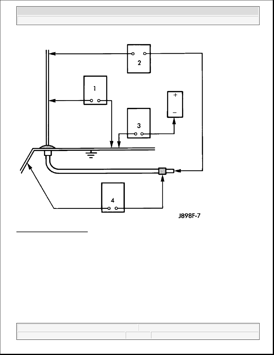
Fig. 3: Antenna Diagnose Tests 
Courtesy of CHRYSLER LLC 

The following four tests are used to diagnose the antenna with an ohmmeter: 

Test 1 - Mast to ground test  

Test 2 - Tip-of-mast to tip-of-conductor test  

Test 3 - Body ground to battery ground test  

Test 4 - Body ground to antenna coaxial cable shield test.  

WARNING:

Disable the airbag system before attempting any steering wheel, steering 
column, seat belt tensioner, side airbag, or instrument panel component 
diagnosis or service. Disconnect and isolate the battery negative (ground) 
cable, then wait two minutes for the airbag system capacitor to discharge 
before performing further diagnosis or service. This is the only sure way 


2007 Dodge Nitro R/T 

2007 ACCESSORIES AND EQUIPMENT Audio/Video - Service Information - Nitro


The ohmmeter test lead connections for each test are shown in the illustration. 

TEST 1 

Test 1 determines if the antenna mast is insulated from ground. Proceed as follows: 

1. Disconnect and isolate the antenna coaxial cable connector behind the right side kick panel.  

2. Touch one ohmmeter test lead to the tip of the antenna mast. Touch the other test lead to known ground. 

Check the ohmmeter reading for continuity.  

3. There should be no continuity. If OK, go to Test 2. If not OK, replace the faulty antenna body and cable.  

TEST 2 

Test 2 checks the antenna conductor components for an open circuit. This test should be performed first on the 
entire antenna circuit, from the antenna mast to the center conductor of the coaxial cable connector at the radio. 
If an open circuit is detected, each of the three antenna conductor components (antenna mast, antenna body and 
cable, instrument panel antenna cable) should be isolated and tested individually to locate the exact component 
that is the source of the open circuit. To begin this test, proceed as follows: 

1. Disconnect the instrument panel antenna cable coaxial connector from the back of the radio.  

2. Touch one ohmmeter test lead to the tip of the antenna mast. Touch the other test lead to the center 

conductor pin of the instrument panel antenna cable coaxial connector for the radio. Check the ohmmeter 
reading for continuity.  

3. There should be continuity. The ohmmeter should register only a fraction of an ohm resistance. High or 

infinite resistance indicates a damaged or open antenna conductor. If OK, go to Test 3. If not OK, isolate 
and test each of the individual antenna conductor components. Replace only the faulty antenna conductor 
component.  

TEST 3 

Test 3 checks the condition of the vehicle body ground connection. To begin this test, proceed as follows: 

1. This test must be performed with the battery positive cable disconnected from the battery. Disconnect and 

isolate both battery cables, negative cable first.  

2. Reconnect the battery negative cable. 

to disable the airbag system. Failure to take the proper precautions could 
result in accidental airbag deployment and possible personal injury.

NOTE:

This model has a two-piece antenna coaxial cable. Tests 2 and 4 must be 
conducted in two steps to isolate an antenna cable problem. First, test the 
primary antenna cable (integral to the antenna body and cable) from the coaxial 
cable connector behind the right side kick panel to the antenna body. Then, test 
the secondary antenna cable (instrument panel antenna cable) from the coaxial 
cable connector behind the right side kick panel to the coaxial cable connector 
at the radio.


2007 Dodge Nitro R/T 

2007 ACCESSORIES AND EQUIPMENT Audio/Video - Service Information - Nitro


3. Touch one ohmmeter test lead to a good clean ground point on the vehicle fender. Touch the other test 

lead to the battery negative terminal post. Check the ohmmeter reading for continuity.  

4. There should be continuity. The ohmmeter should register less than one ohm resistance. High or infinite 

resistance indicates a loose, corroded, or damaged connection between the battery negative terminal and 
the vehicle body. If OK, go to Test 4. If not OK, check the battery negative cable connection to the 
vehicle body and the radio noise suppression ground strap connections to the engine and the vehicle body 
for being loose or corroded. Clean or tighten these connections as required.  

TEST 4 

Test 4 checks the condition of the connection between the antenna coaxial cable shield and the vehicle body 
ground as follows: 

1. Disconnect and isolate the antenna coaxial cable connector behind the right side kick panel.  

2. Touch one ohmmeter test lead to a good clean ground point on the vehicle fender. Touch the other test 

lead to the outer crimp on the antenna coaxial cable connector. Check the ohmmeter reading for 
continuity.  

3. There should be continuity. The ohmmeter should register less than one ohm resistance. High or infinite 

resistance indicates a loose, corroded, or damaged connection between the antenna body and the vehicle 
body or between the antenna body and the antenna coaxial cable shield. If not OK, clean the antenna body 
to fender mating surfaces and tighten the antenna cap nut to specifications.  

4. Check the resistance again with an ohmmeter. If the resistance is still more then one ohm, replace the 

faulty antenna body and cable.  

REMOVAL 

ANTENNA BODY AND CABLE 

1. Disconnect the battery negative cable.  

2. Remove the headliner. Refer to REMOVAL .  

3. Disconnect the electrical connectors.  

4. Remove the routing clips and remove the cable.  

INSTALLATION 

ANTENNA BODY AND CABLE 

1. Install the cable and routing clips.  

2. Connect the electrical connectors.  

3. Install the headliner. Refer to INSTALLATION .  

4. Connect the battery negative cable.  

ANTENNA-SATELLITE 

OPERATION 


2007 Dodge Nitro R/T 

2007 ACCESSORIES AND EQUIPMENT Audio/Video - Service Information - Nitro


ANTENNA - SATELLITE RADIO

The satellite receiver is housed within the radio and is no longer a separate module. The satellite radio antenna 
receives signals from orbiting satellites and sends these signals to the radio. The satellite radio antenna must 
have open space in which to operate. Items carried on the roof, parking inside etc. can have an effect on the 
antenna's ability to receive signals. 

REMOVAL 

ANTENNA BODY AND CABLE 

Fig. 4: Removing Antenna 
Courtesy of CHRYSLER LLC 

1. Disconnect the battery negative cable.  

2. Lower the rear section of the headliner to gain access the antenna, ensuring that the headliner does not 

crease. Refer to REMOVAL .  

3. Remove the mounting fastener.  

4. Disconnect the electrical connectors and remove the antenna.  

INSTALLATION 

ANTENNA BODY AND CABLE 


2007 Dodge Nitro R/T 

2007 ACCESSORIES AND EQUIPMENT Audio/Video - Service Information - Nitro


Content   ..  302  303  304  305   ..