Dodge Durango (HB). Manual - part 960


  Index      Dodge     Dodge Durango (HB) - service repair manual 2005 year


Search            


Content   ..  958  959  960  961   ..


Dodge Durango (HB). Manual - part 960


P2099-DOWNSTREAM FUEL TRIM SYSTEM 2 RICH (CONTINUED)
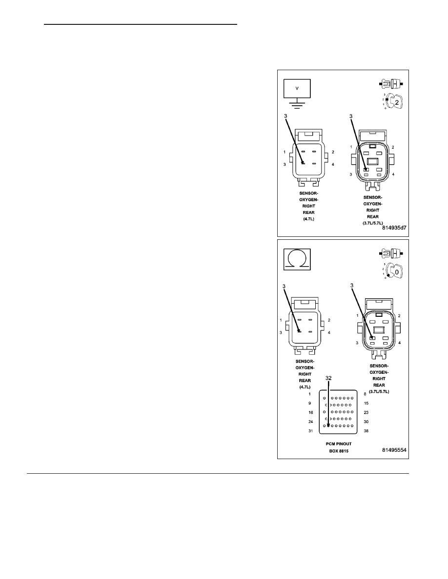
7.

(K904) O2 RETURN DOWNSTREAM CIRCUIT

Measure the voltage on the (K904) O2 Return Downstream circuit in
the O2 Sensor harness connector.

Is the voltage at 2.5 volts?

Yes

>> Check the fuel system for contaminants.

Perform the POWERTRAIN VERIFICATION TEST. (Refer
to 9 - ENGINE - STANDARD PROCEDURE)

No

>> Check the (K904) O2 Return Downstream circuit for a

short to ground, open, or short to voltage. Inspect the O2
Sensor connector and the PCM harness connector. If OK,
replace and program the Powertrain Control Module per
Service Information.

Perform the POWERTRAIN VERIFICATION TEST. (Refer
to 9 - ENGINE - STANDARD PROCEDURE)

HB

ENGINE ELECTRICAL DIAGNOSTICS

9 - 839

P2100-ELECTRONIC THROTTLE CONTROL MOTOR CIRCUIT

9 - 840

ENGINE ELECTRICAL DIAGNOSTICS

HB

P2100-ELECTRONIC THROTTLE CONTROL MOTOR CIRCUIT (CONTINUED)

For the Engine circuit diagram (Refer to 9 - ENGINE - SCHEMATICS AND DIAGRAMS).

For a complete wiring diagram Refer to Section 8W.

When Monitored:
With the ignition on and the ETC Motor is not in Limp Home mode.

Set Condition:
When the PCM detects an internal error or a short between the ETC Motor- and ETC Motor + circuits in the
ETC Motor Driver. One trip fault. ETC light is flashing.

Possible Causes

THROTTLE PLATE / BORE INSPECTION

(K447) ETC POSITIVE CIRCUIT SHORTED TO BATTERY VOLTAGE

(K448) ETC NEGATIVE CIRCUIT SHORTED TO BATTERY VOLTAGE

(K447) ETC POSITIVE CIRCUIT SHORTED TO THE (K448) ETC NEGATIVE CIRCUIT

(K447) ETC POSITIVE CIRCUIT OPEN

(K447) ETC POSITIVE CIRCUIT SHORTED TO GROUND

(K448) ETC NEGATIVE CIRCUIT OPEN

(K448) ETC NEGATIVE CIRCUIT SHORTED TO GROUND

LOW BATTERY VOLTAGE

ETC MOTOR/THROTTLE BODY

PCM

Always perform the Pre-Diagnostic Troubleshooting procedure before proceeding. (Refer to 9 - ENGINE -
DIAGNOSIS AND TESTING).

Diagnostic Test

1.

ACTIVE DTC

Ignition on, engine not running.

NOTE: If the P2100 is intermittent, it is possible that the controller is overheating in extreme hot tempera-
tures, and this is considered a normal protection operation. No repair is necessary.

NOTE: Low battery voltage can also cause excessive current draw, in very hot and very cold ambient tem-
peratures. Make sure the battery can pass a Load test before continuing.
With a scan tool, read DTCs.

Look closely at the temperatures at which this DTC set.

Is the DTC active at this time?

Yes

>> Go To 2

No

>> Refer to the INTERMITTENT CONDITION Diagnostic Procedure.

Perform the POWERTRAIN VERIFICATION TEST. (Refer to 9 - ENGINE - STANDARD PROCEDURE)

HB

ENGINE ELECTRICAL DIAGNOSTICS

9 - 841

P2100-ELECTRONIC THROTTLE CONTROL MOTOR CIRCUIT (CONTINUED)

2.

THROTTLE PLATE INSPECTION

Turn the ignition off.

Remove the Air Cleaner Assembly from the Throttle Body.

Check for any signs of a foreign material (ice or dirt) on the Throttle Plate or in the bore causing the Throttle Plate
to stick.

Were any signs of foreign material or scoring of the throttle plate or bore found?

Yes

>> Remove the debris if possible or replace the Throttle Body Assembly. Disconnect the Battery when

replacing the Throttle Body Assembly. After installation is complete, use a scan tool and select the ETC
RELEARN function.

Perform the POWERTRAIN VERIFICATION TEST. (Refer to 9 - ENGINE - STANDARD PROCEDURE)
d

No

>> Go To 3

3.

(K447) ETC POSITIVE CIRCUIT SHORTED TO BATTERY VOLTAGE

Turn the ignition off.

Disconnect the Throttle Body harness connector.

Disconnect the C2 PCM harness connector.

Ignition on, engine not running.

CAUTION: Do not probe the PCM harness connectors. Probing
the PCM harness connectors will damage the PCM terminals
resulting in poor terminal to pin connection. Install Miller Special
Tool #8815 to perform the diagnostics.
With a 12-volt test light connected to ground, probe the (K447) ETC
Positive circuit at the appropriate terminal of special tool #8815.

Does the test light illuminate brightly?

Yes

>> Repair the short to battery voltage on the (K447) ETC

Positive circuit.

Perform the POWERTRAIN VERIFICATION TEST. (Refer
to 9 - ENGINE - STANDARD PROCEDURE)

No

>> Go To 4

4.

(K448) ETC NEGATIVE CIRCUIT SHORTED TO BATTERY
VOLTAGE

Using a 12-volt test light connected to ground, probe the (K448) ETC
Negative circuit at the appropriate terminal of special tool #8815.

Does the test light illuminate brightly?

Yes

>> Repair the short to battery voltage in the (K448) ETC Neg-

ative circuit.

Perform the POWERTRAIN VERIFICATION TEST. (Refer
to 9 - ENGINE - STANDARD PROCEDURE)

No

>> Go To 5

9 - 842

ENGINE ELECTRICAL DIAGNOSTICS

HB


Content   ..  958  959  960  961   ..