Index Dodge Dodge Durango (HB) - service repair manual 2005 year
Search
Content .. 938 939 940 941 ..
Dodge Durango (HB). Manual - part 940
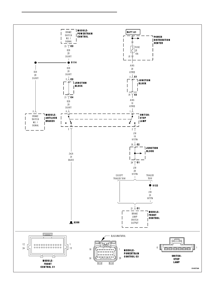
P1572-BRAKE PEDAL STUCK ON
HB
ENGINE ELECTRICAL DIAGNOSTICS
9 - 759