Index Dodge Dodge Durango (HB) - service repair manual 2005 year
Search
Content .. 914 915 916 917 ..
Dodge Durango (HB). Manual - part 916
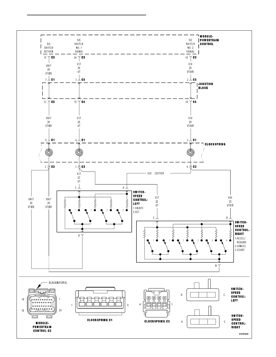
P0592-SPEED CONTROL SWITCH 2 CIRCUIT LOW
HB
ENGINE ELECTRICAL DIAGNOSTICS
9 - 663